Water Maker Installation
This page covers both the initial installation and the upgrade to the water maker installation. These are herein referred to as the Water Maker First Pass and the Water Maker Second Pass. The first pass, as noted in this page, was very successful, and we had really good service from the unit. However, during the trip back from Guatemala to Houston via Isla Mujeres in 2006, the system developed a problem. As we were crossing the Gulf, one of the valves in the Hotsy high-pressure pump went bad and needed to be replaced. The pump continued to function, but it was very noisy and did not produce the 15-GPH of which it was capable. The other item that needed work was the maintainability of the FIRST PASS system. It was okay, but needed some work. I was determined to get the high-pressure pump repaired, and I wanted to collect spares for the pump, and make the entire system more maintainable.
When I speak of making the system more maintainable, I am referring to ease of access to the system itself. I wanted to be able to change the sediment filters quickly and easily. I also wanted to be able to check the oil in the high-pressure pump, and be able to top off the valve oilers quickly and easily.
The parts lists were updated in October of 2012. The First Pass parts list has been updated as much as possible. The prices reflected are the 2004 prices. The links to web pages have been updated to the present time. The link to Blue Water Ship Store has been eliminated, because the store went out of business. I have fixed the links to Great Water , but they do not make the water maker control panel, or other manual parts. All of their water makers are of the automatic type. The Jabsco Sensor Max VSD pump is only sold at West Marine via a special order.
The Second Pass parts list has all the web pages updated and the link to Blue Water Ships Store has been eliminated, because the store went out of business. The prices reflect October 2012 prices. The number of parts used has been changed to reflect the present system.
The difficult decision about the water maker project was determining what type of power resource to use, i.e., 12 VDC, engine-driven, or 110 VAC. Each type has its advantages. The engine-driven unit was out for me because there was no room on the front of the main engine for a power take-off. The generator had already been installed, and if I went wth a 12VDC unit, I would be running the generator to charge the batteries. The decision was to go with a 110 VAC unit.
Buying a water maker is a very expensive investment that can run anywhere from $4,500.00 to $7,000.00, or more. This was way beyond my budget. I had talked to the friends with whom we went cruising in The Bahamas in 2003 and with some other friends around the Clear Lake area, about the expense problem. The consensus of opinions was that one could build a good unit out of off-the-shelf parts, and that would save a bundle. Most of the water makers sold have a bunch of bells and whistles that allow making water to be very easy and automatic, but those options drive up the price of the unit substantially. With the exceptions of the feed pump and the high-pressure pump, I elected to do everything else manually. I would use my tongue to test the water quality. There were some numbers being thrown around that suggested one could build a water maker for $500.00. It sounded good, but this turned out to be unrealistic. I was hoping that I could get the job done for between $1,500.00 and $1,800.00. Even this figure turned out to be too low, but I hoped to be able to keep it under $2,200.00, and I was able to do so. You can look at the parts list to see a list of the parts I used for the project. This list includes part numbers, prices, and links to each vendor and/or manufacturer of the part. If you are interested in the actual construction of the water maker, please refer to the drawing in which I explain the steps of the project.
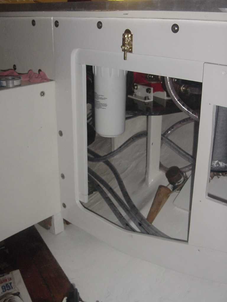
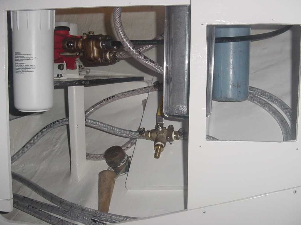
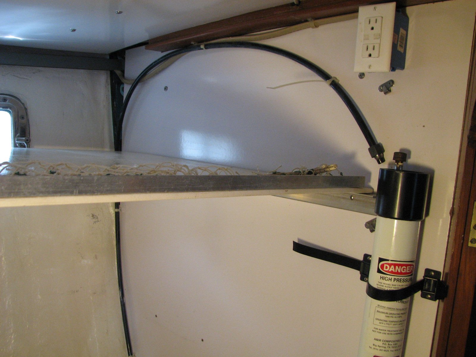
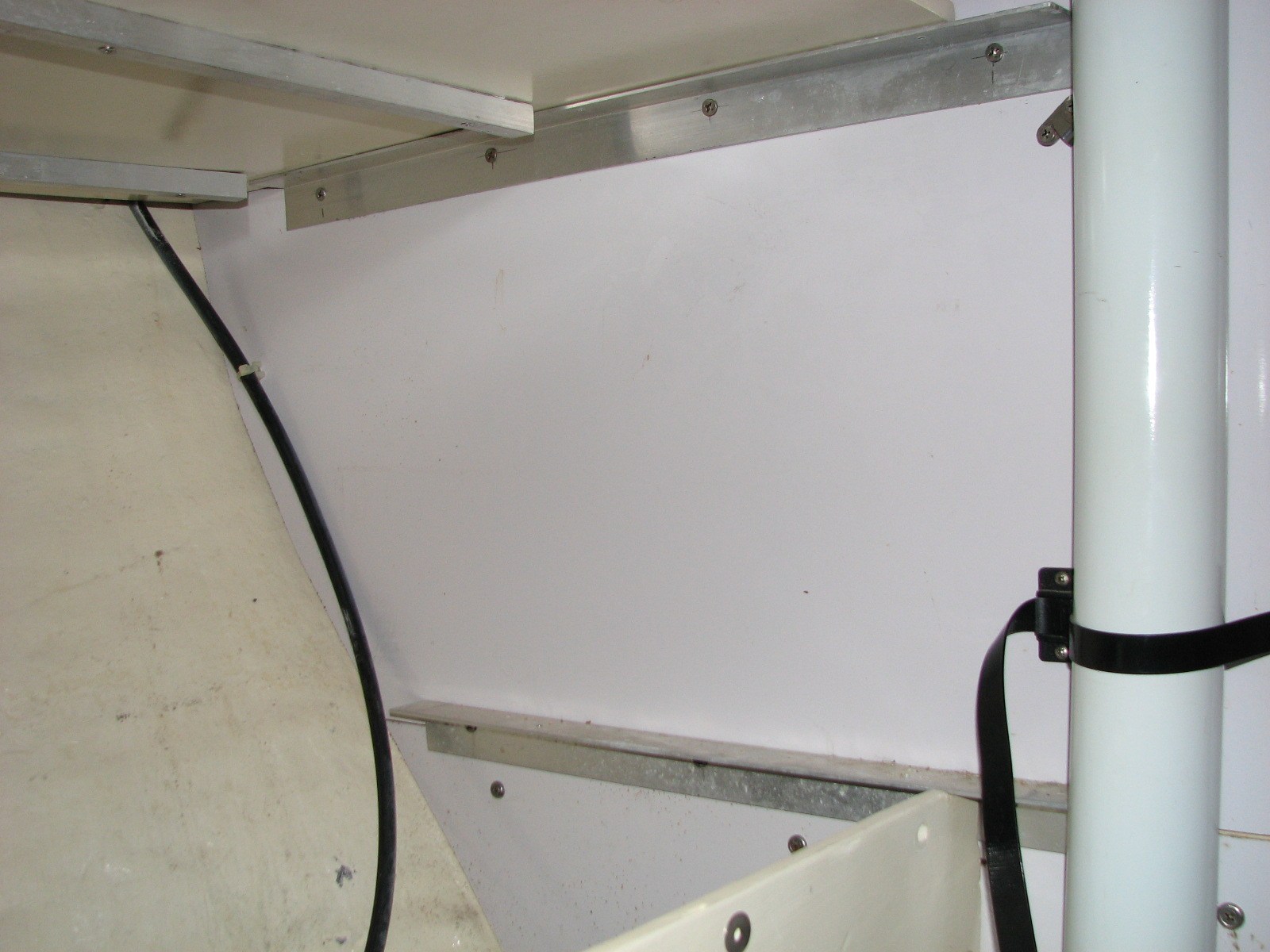
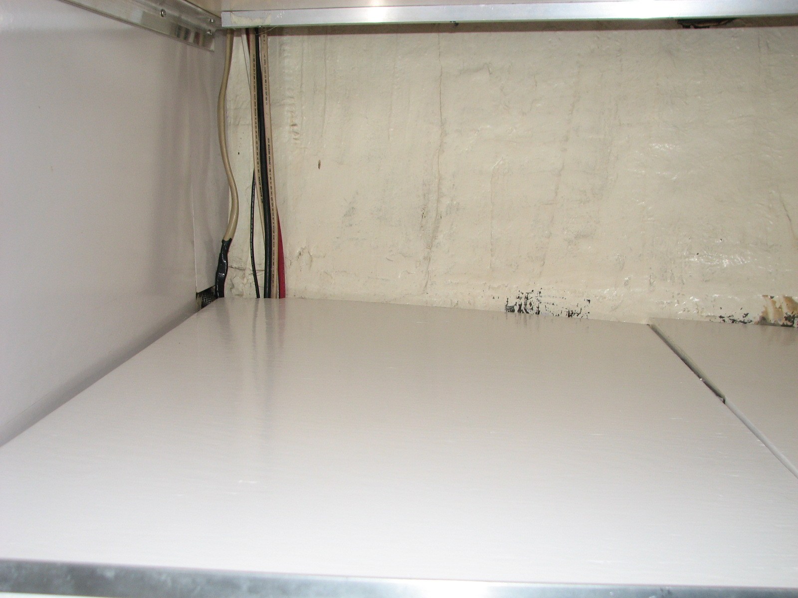
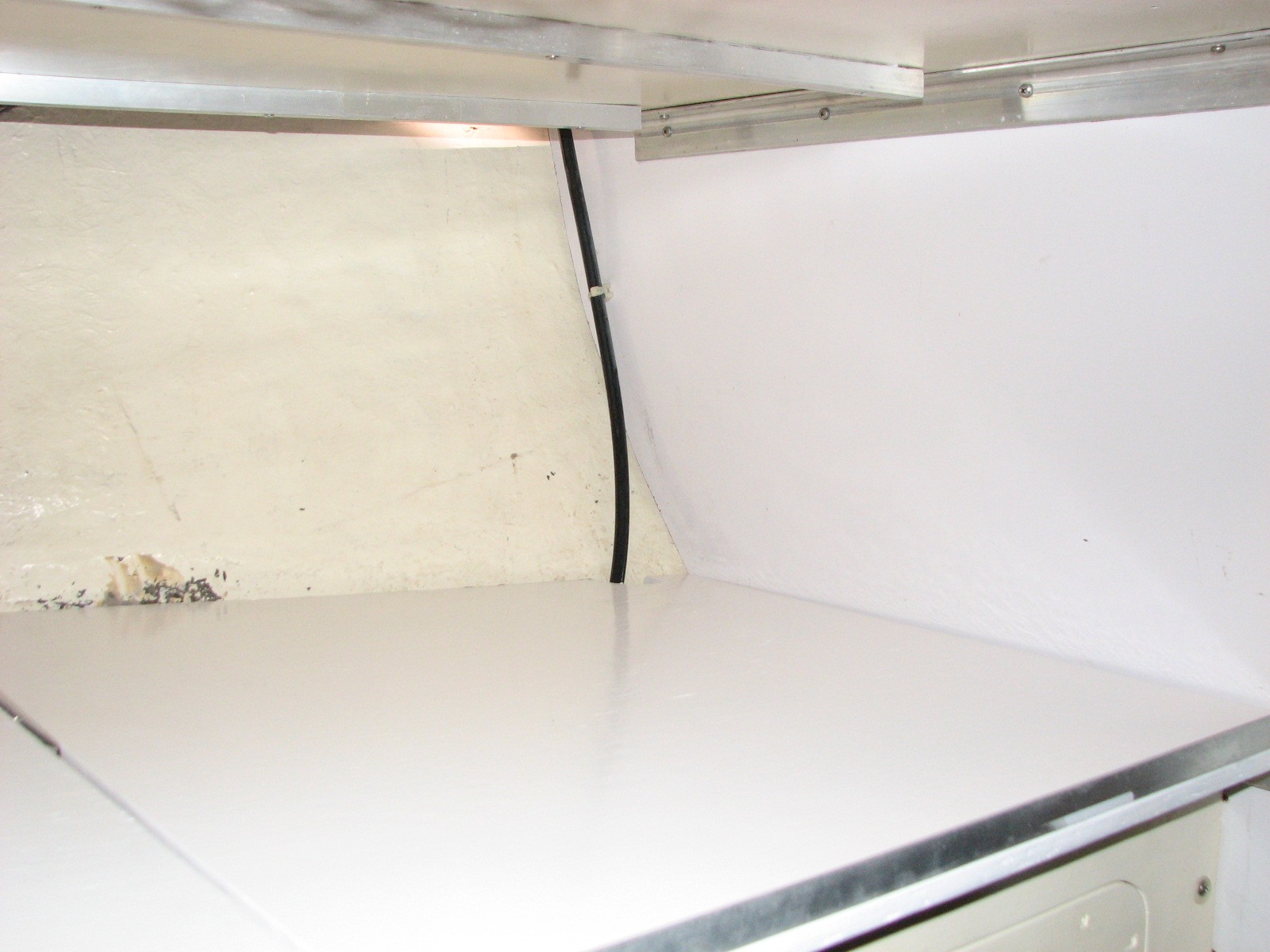
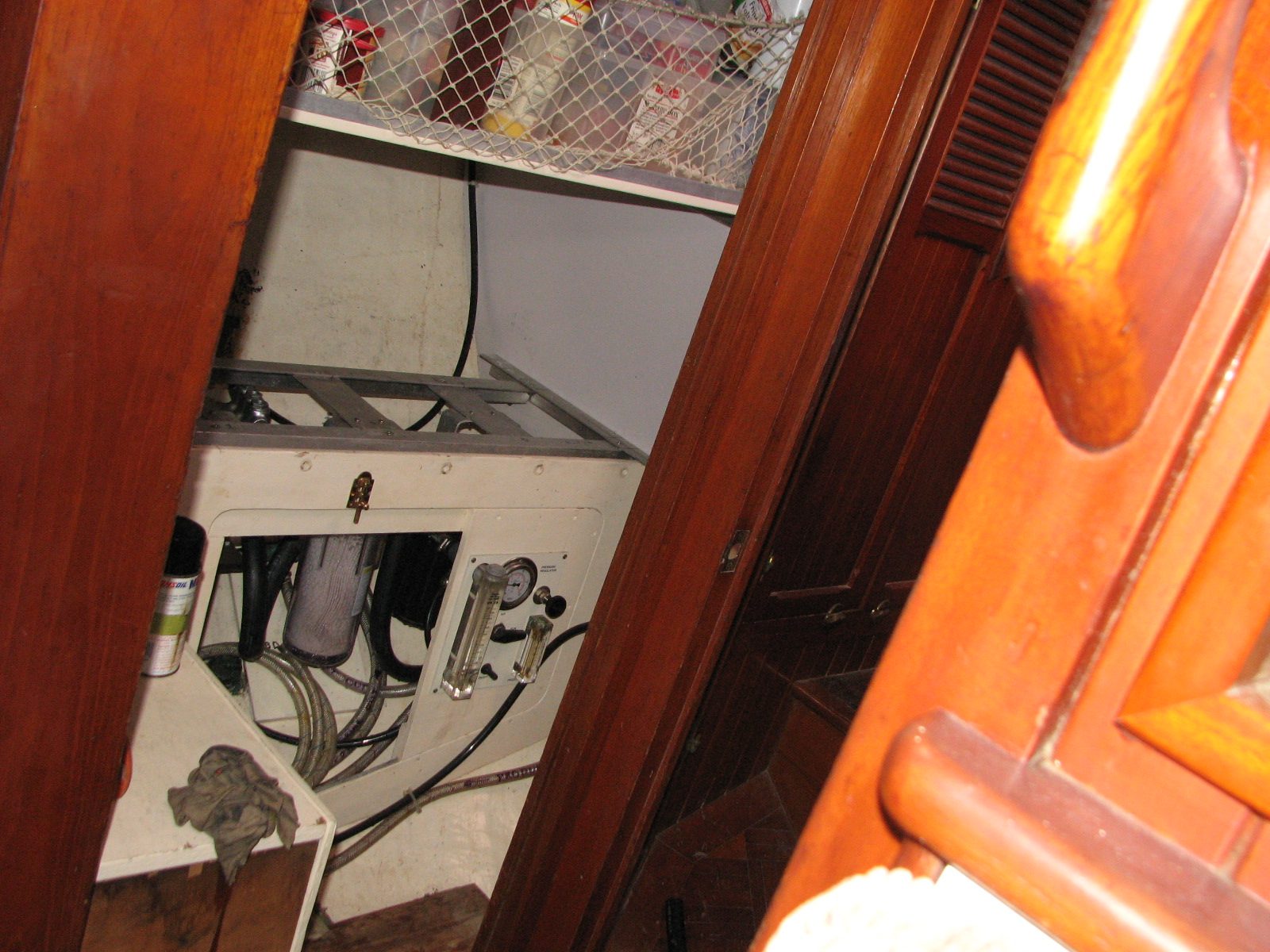
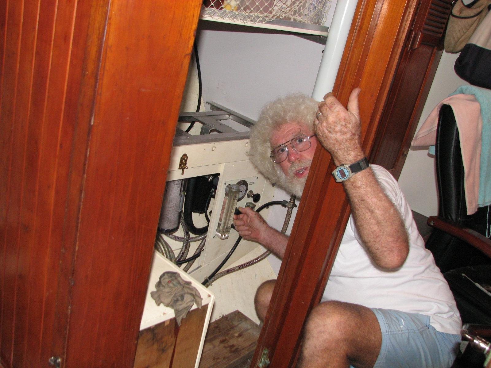
I decided to put the water maker under the bottom shelf in our 'pantry', which is actually a converted second head. I already had a 12 VDC refrigeration system on board, and had some of the ice-maker controls in the same area. I did not have to move the refrigeration system, but I did have to m ove the ice-maker controls. I emptied the bottom shelf in the 'pantry' and temporarily removed it so I could have room in which to work. I then moved all of the ice-maker controls for the ice-maker into the area where the ice-maker compressor was installed. I was able to get this done and confirm that the ice-maker was still functioning!!
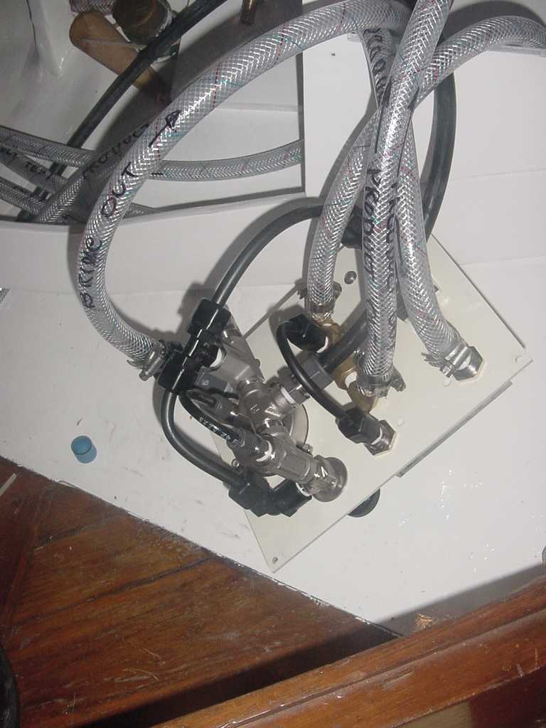
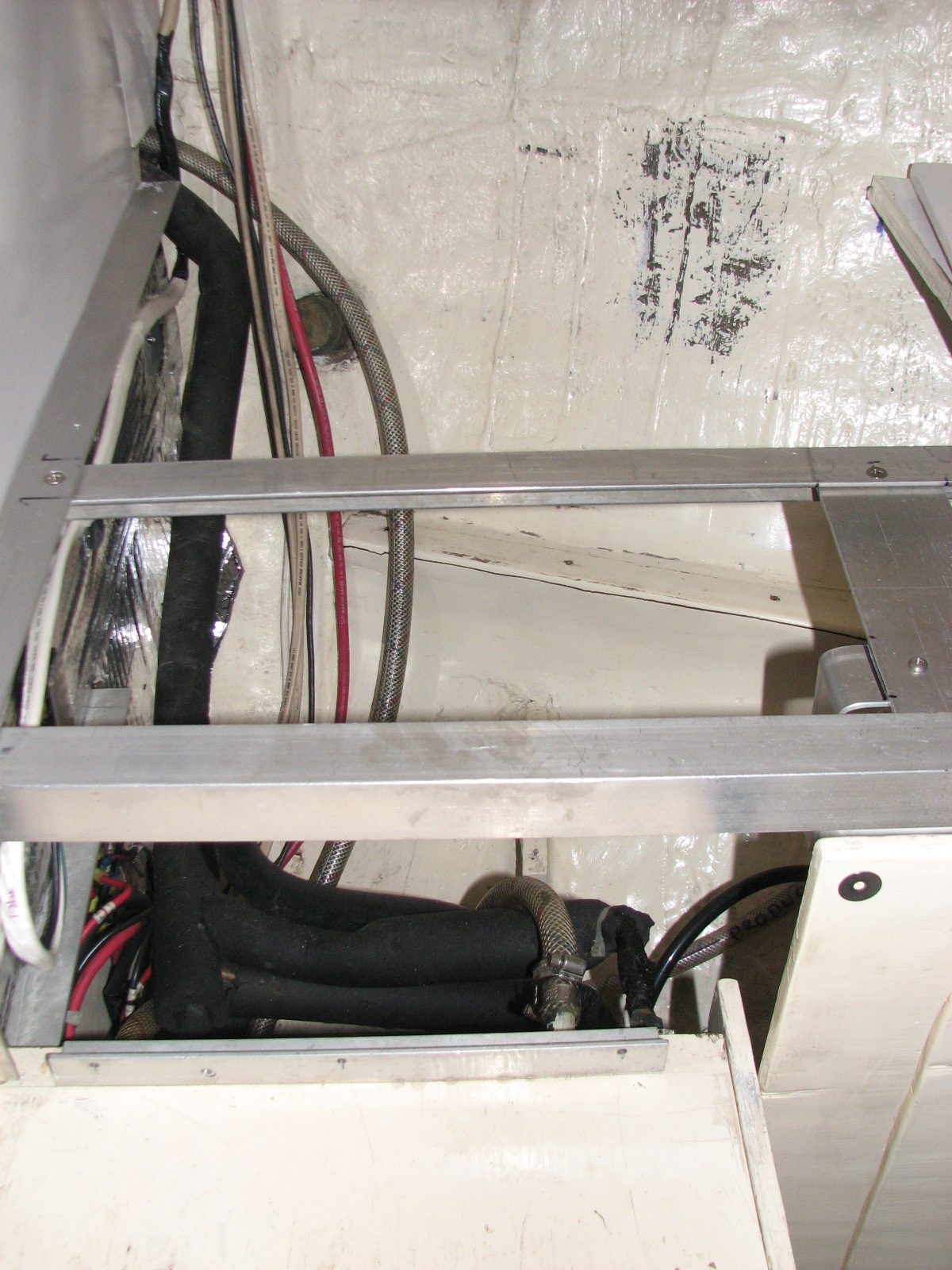
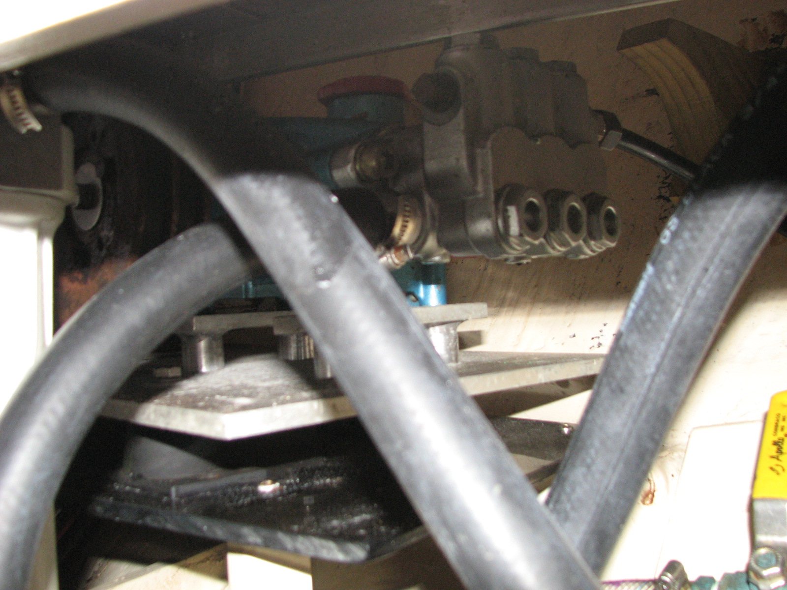
I decided that the deck plate for the motor and the high-pressure pump should be made of plastic so that I did not have to contend with possible rot in a wooden deck or corrosion with a metal deck. I was able to find a 1/2" piece of acrylic to which I could bolt down the motor and the high-pressure pump. I used carriage bolts to bolt the parts down. Because I had used a plastic deck, I heated the bolts and then dropped them into the holes. Instantly, I had a square hole for the carriage bolt to lock into. Once I got the deck made, I fabricated supports for the deck that attached to the hull. These supports were made of fiberglass. When the plate was built, and the motor/high-pressure pump deck was firmly bolted into place, it was a matter of getting electricity to the motor, and water to and from the water pump.
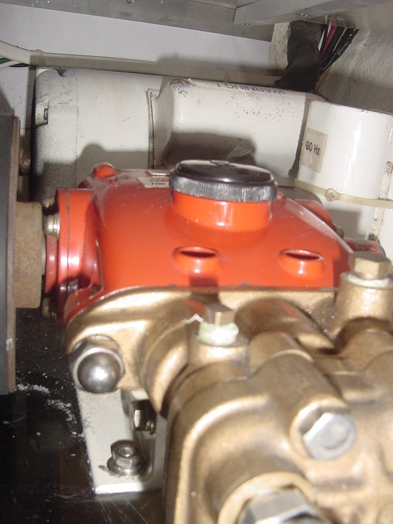
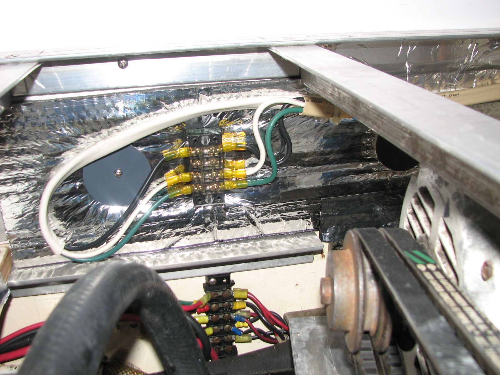
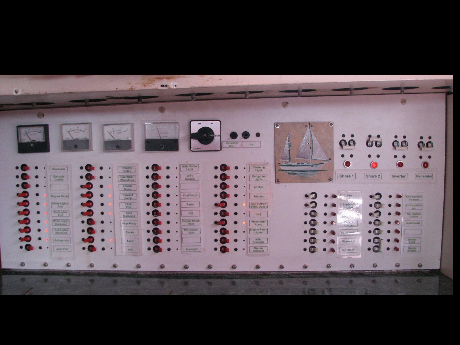
The electrical wiring was very straight forward. I wired a breaker from the AC side of the electrical panel and ran 10-gauge wire to the motor. The motor is a 1 1/2 HP 110 VAC Baldor unit.
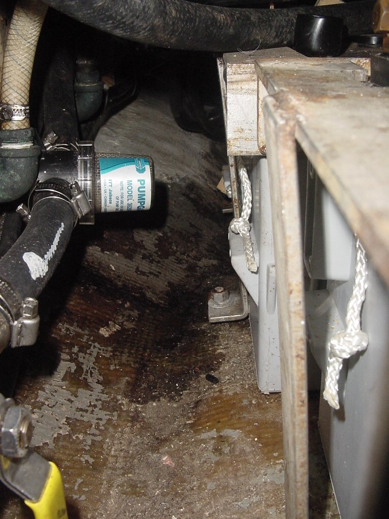
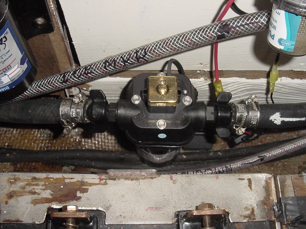
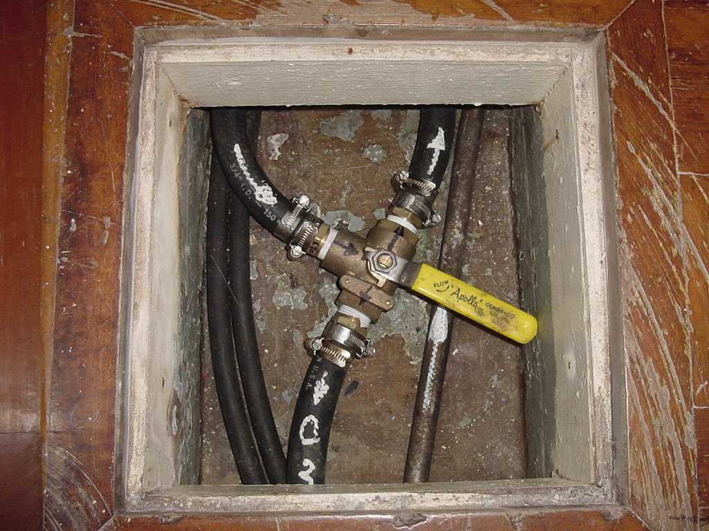
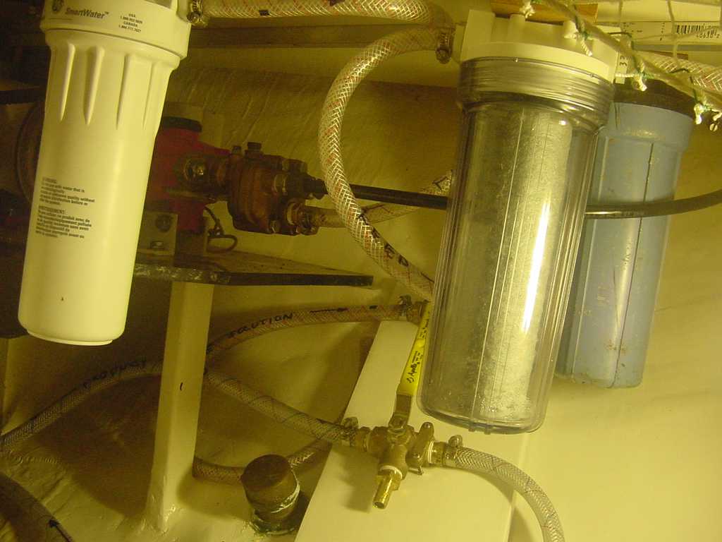
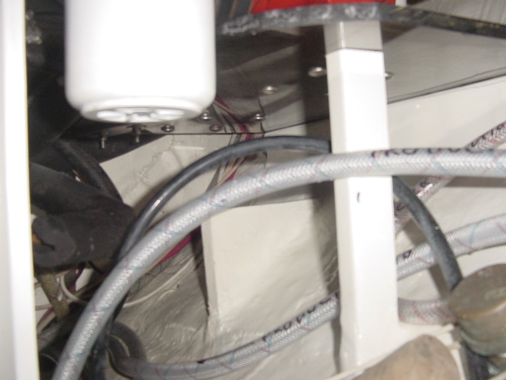
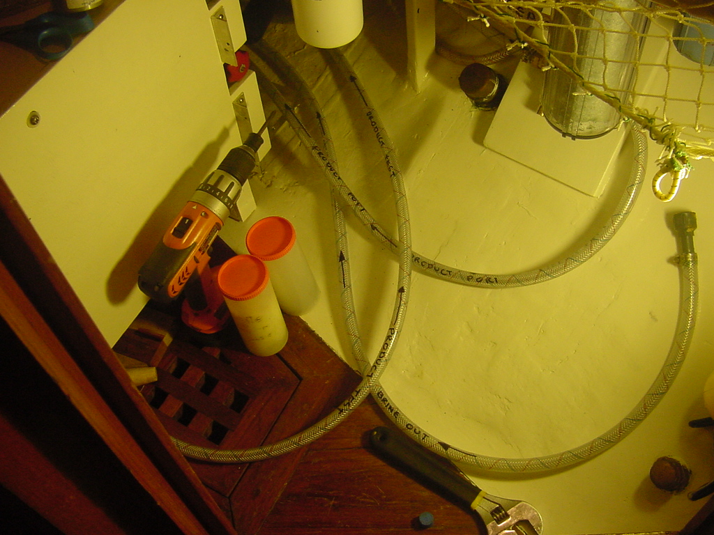
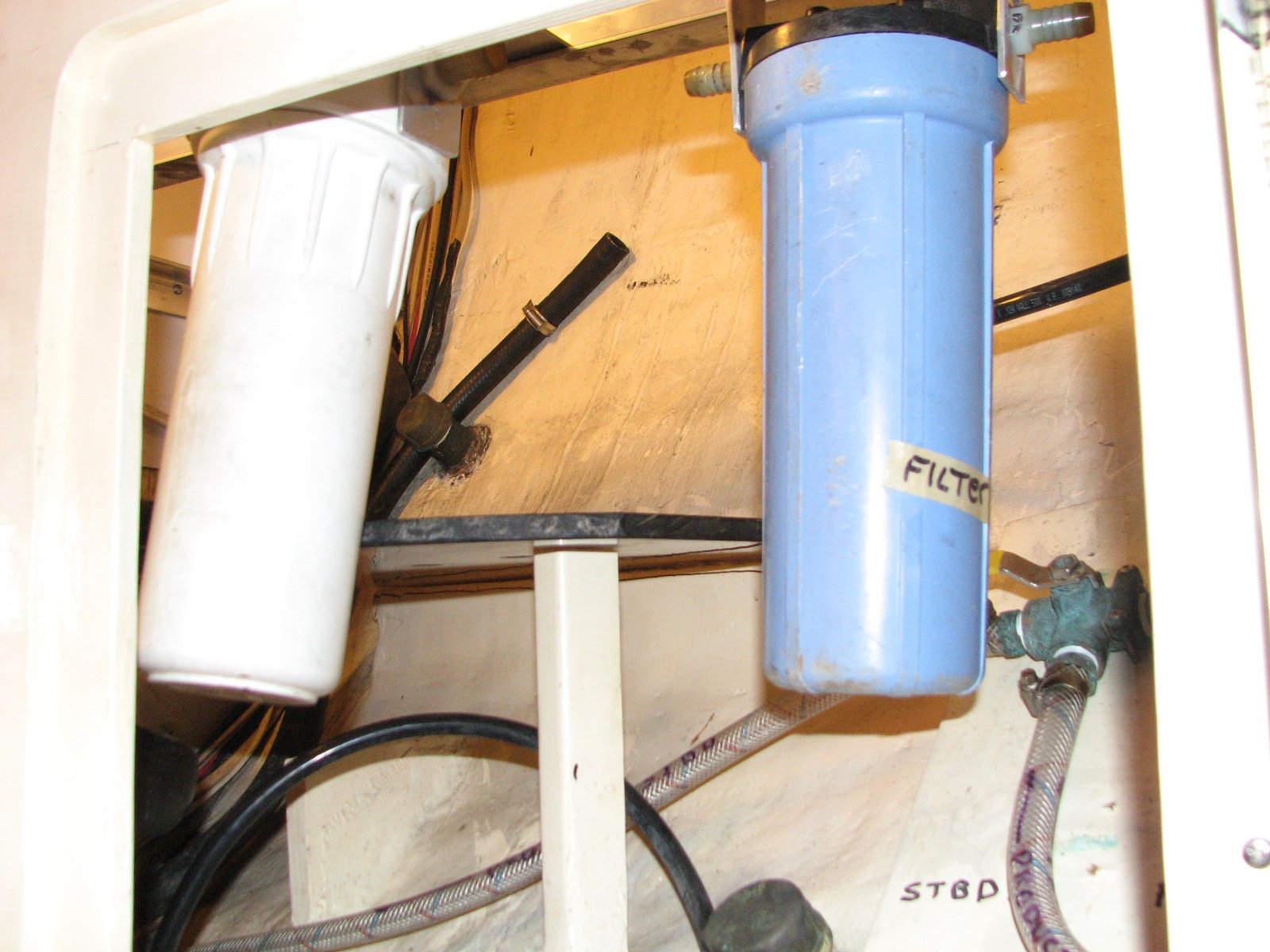
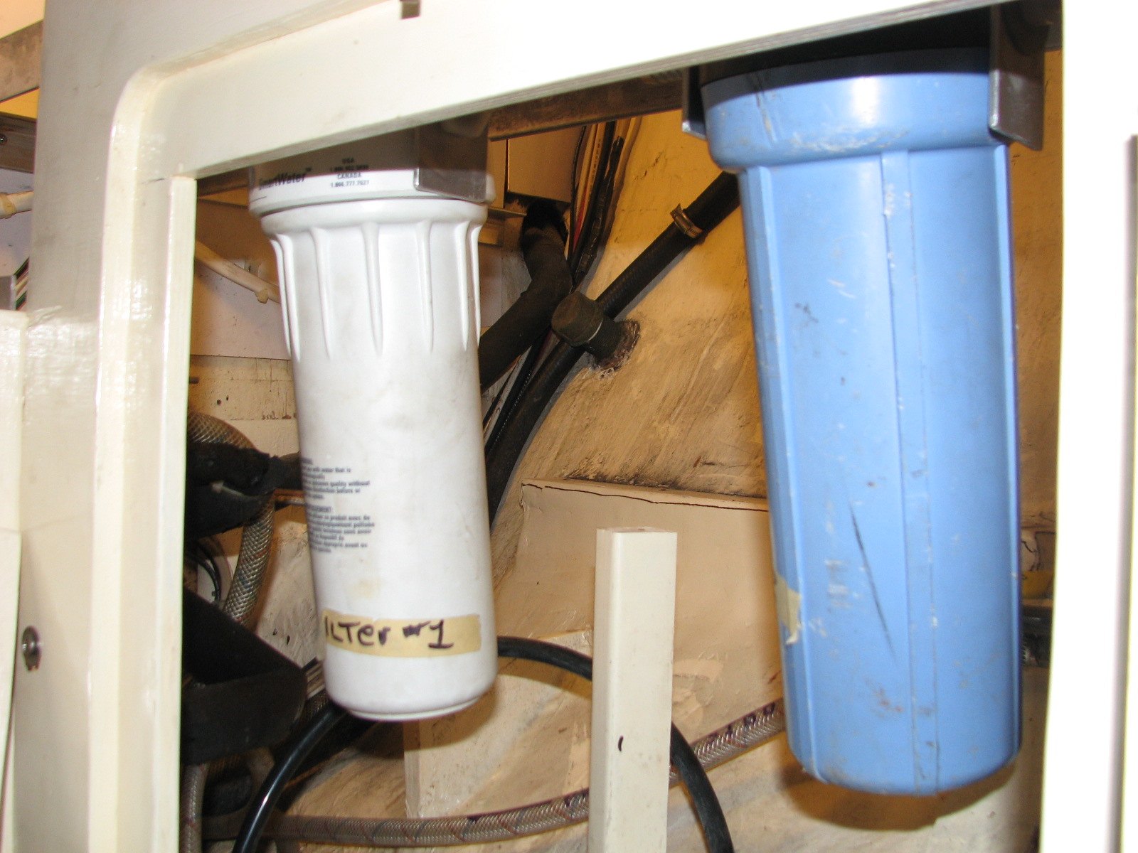
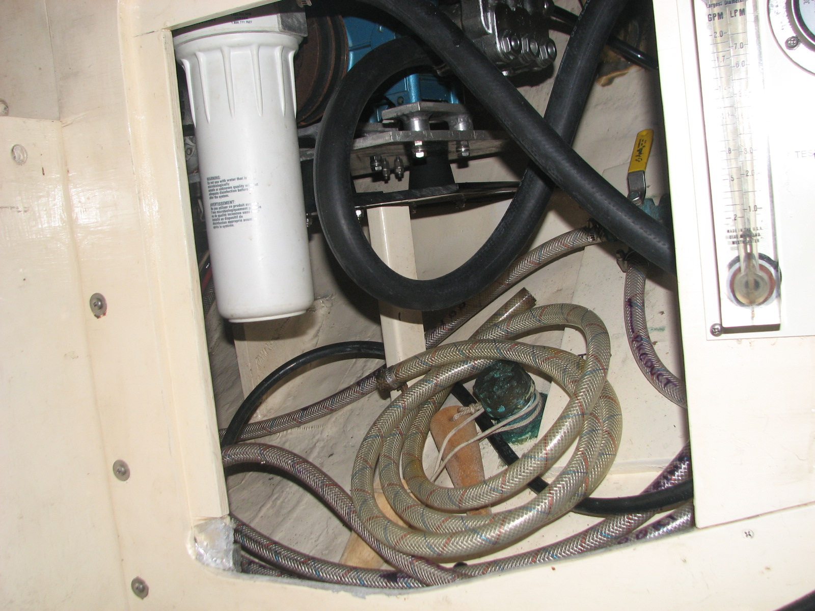
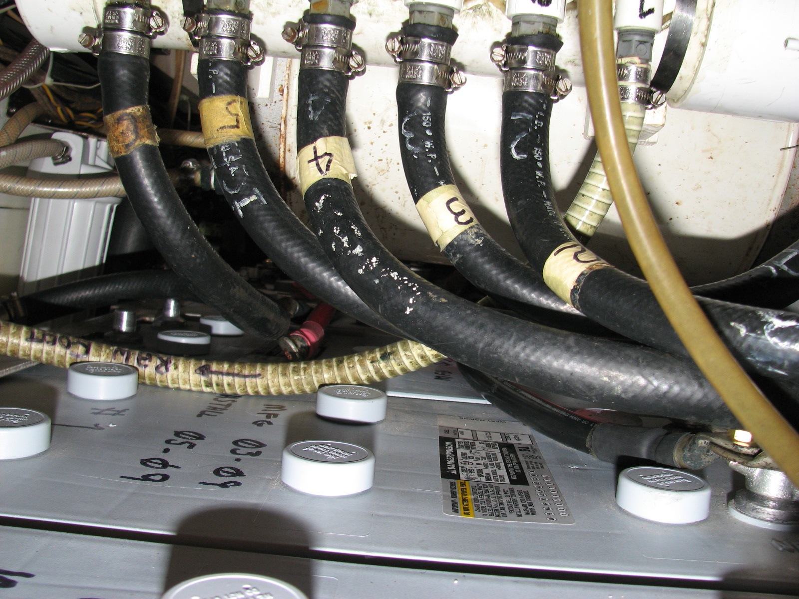
Getting the water to and from the high-pressure pump was much more involved. The water flow is illustrated in the drawing. I will explain some of the decisions made. The first decision was to determine from where to get the raw water. I did not want to add another pump to the boat, so I decided to use the raw-water wash-down pump as the feed pump to the water maker. As the raw-water enters the boat, it goes through a strainer, and then into a PVC manifold. From the PVC manifold, the raw-water goes through a second strainer before entering the wash-down pump. I had to upgrade the pump that I was using as it did not have the necessary capacity. Based on input from Great Water Inc, I used the Jabsco Sensor Max as the feed pump. I made it possible to switch from fresh water to the raw-water wash-down system so we would be able use fresh water to hose off the boat, and could shower on deck after a dive trip. I also needed a way to get fresh water into the Reverse Osmosis (RO) membrane for those occasions on which I would not be able to use the system for 30 days or more, in which case one must pickle the system, or less than 30 days, in which case one would leave fresh water in the system. I installed a three-way valve on the input to the feed pump/raw-water wash-down pump. This is where my drawing starts. Following the feed pump, there is a second three-way valve that switches the output of the feed pump to either the on-deck wash-down outlet or to the water maker. The water that goes through the water maker goes through three filters. The first filter is a 30-micron sediment filter, the second filter is a five-micron sediment filter, and the third filter is a petroleum filter. I know that may sound like overkill, but you know me by now!! They still call me “Overkill Kenworthy”. After the last filter, there is a third three-way valve. The output from this valve goes to the high-pressure pump. This valve can switch the water from the filters, or allow a pickling solution to be pumped into the system if the system is not going to be used for over thirty days.
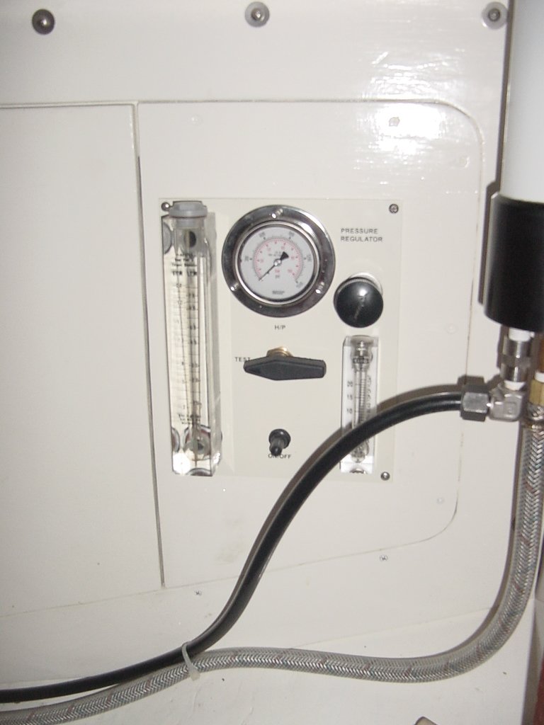
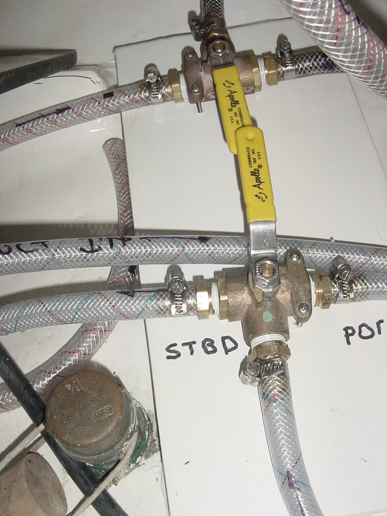
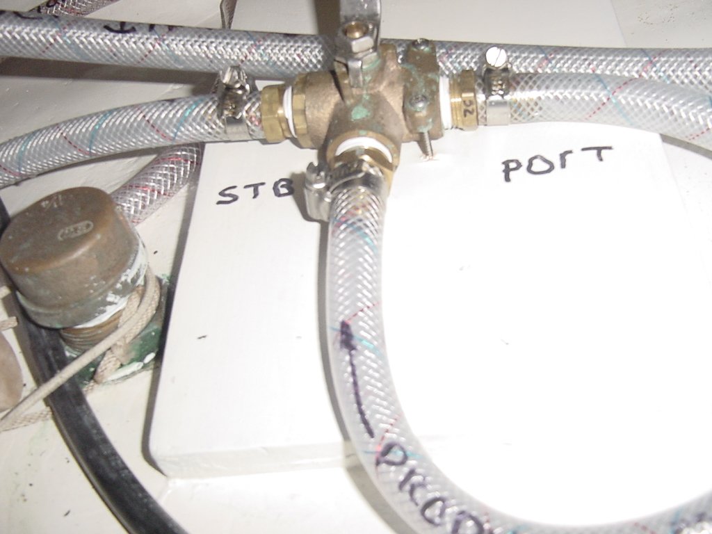
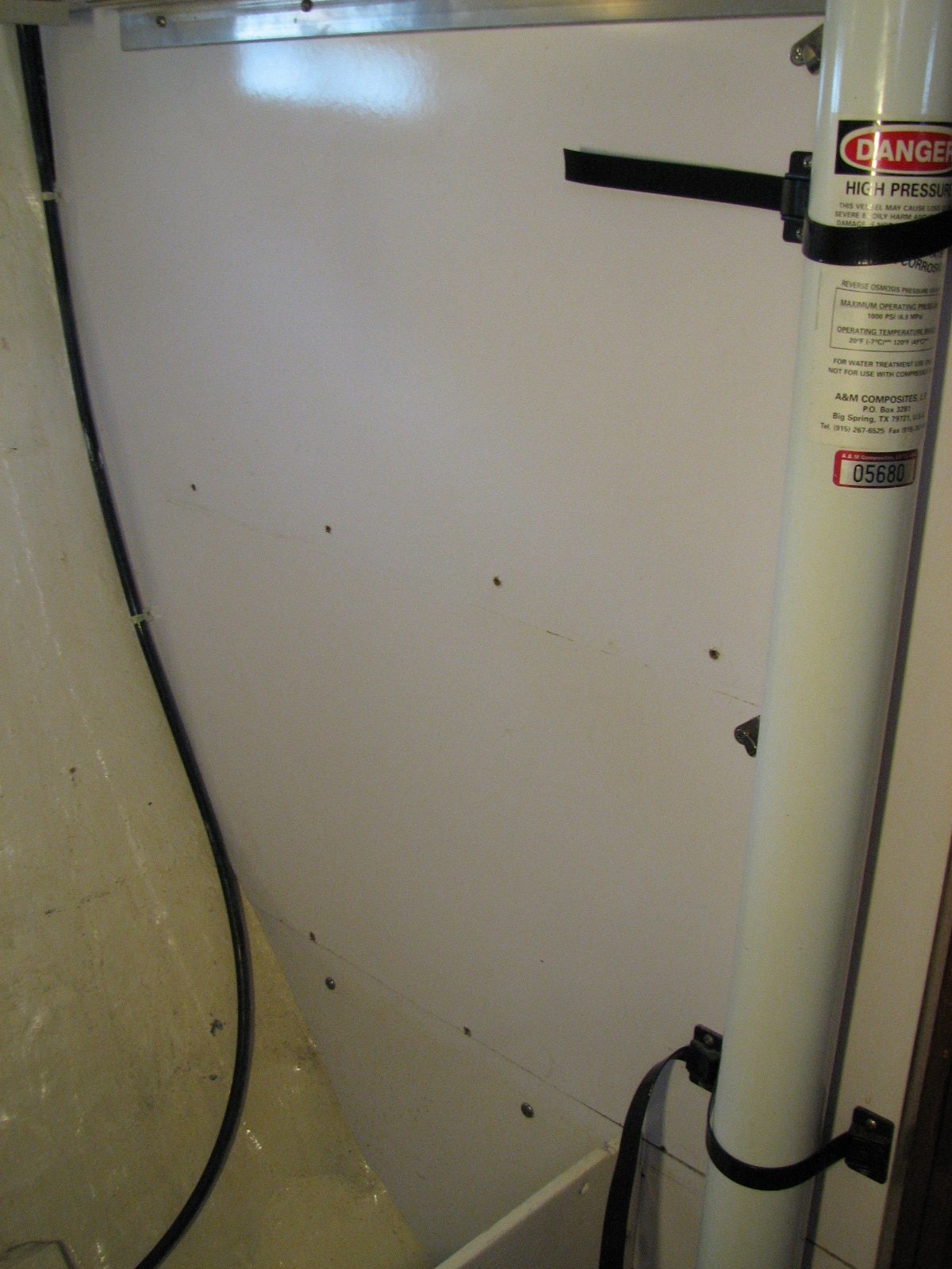
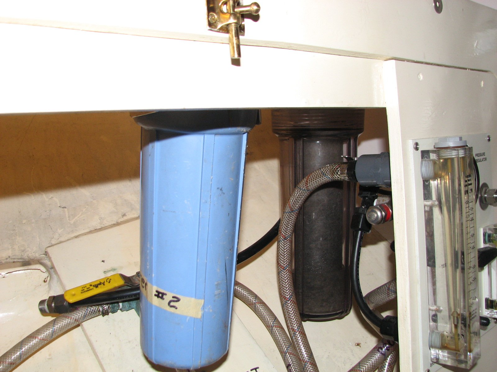
From the pump, the water enters the RO membrane. From the RO membrane, the water goes to the adjustment valve, which is on the control panel. This valve adjusts the pressure at which the water flows through the RO membrane. I usually manually adjust the water pressure to be between 600 and 700 PSI. There are two outputs out from the RO membrane: one is raw water (the brine), and the other is the product water (the fresh water). The raw water goes through the adjustment valve and through a flow meter, and, from there, to an overboard discharge. The product water goes through a flow meter to a three-way valve on the water maker control panel. This valve allows me to switch the product water to the galley sink outlet so that I can taste it for quality assurance. Then I change the valve and send the water into the fresh water tanks. The output that goes into the fresh water tanks goes through a three-way valve that switches between the port and starboard tanks. The input to the fresh water tanks goes through the fill hoses, and into the tanks. When the tanks are full, the excess product water overflows overboard through the tank overflow hoses on deck. All the fresh water tank overflow hoses were replaced during the installation.
So far, the system has worked great. It draws about 10 amps ACV when it is running at 700 PSI. At this setting, I am getting about 15 GPH of product water. Depending on the boat's location, and the amount of sediment in the water, the first sediment filter has to be changed frequently, but I am very pleased with the system. If I had to do it over again, I would put some kind of sound-proofing around the motor and high-pressure pump as they are a bit noisy. I may do that in the future.
|
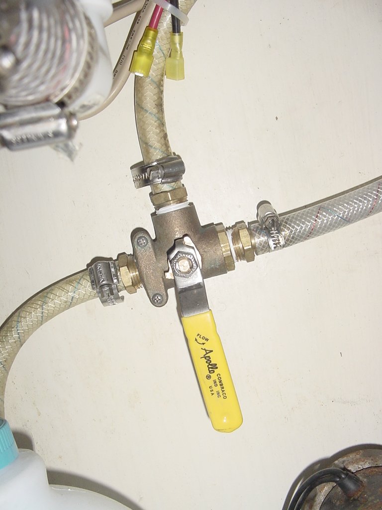
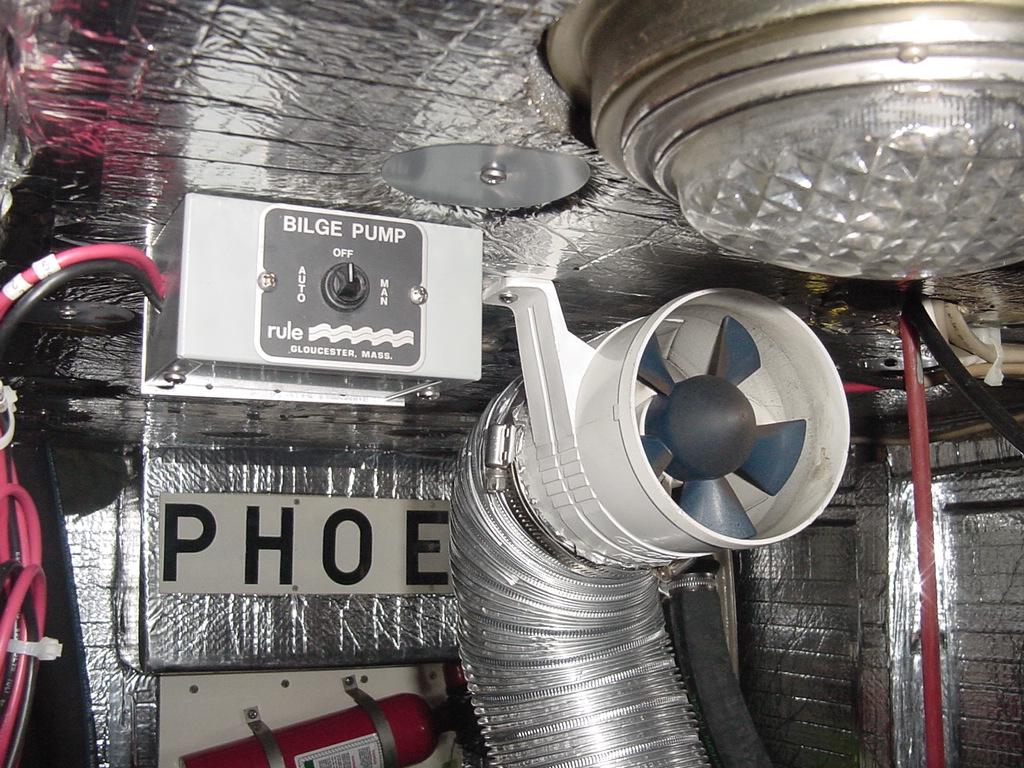
Valve to switch output of lift
pump to wash down or water maker |
I also run the pickling solution through the sediment filters to clear out the tiny organisms in the raw water filters so they will not start growing in the sediment filters. Otherwise, the sediment filter gets very nasty and smelly. My strong recommendation is that, if you are pickling the membrane filter, you completely remove the sediment filters, and then install new sediment filters when you want to use the water maker again.
Since I knew I would be taking the system apart to repair the high pressure pump, I pickled the membrane filter, and sealed the pressure vessel, to keep the membrane filter sealed. Then I removed the deck on which the Baldor electric motor and the Hotsy high pressure pump were attached.
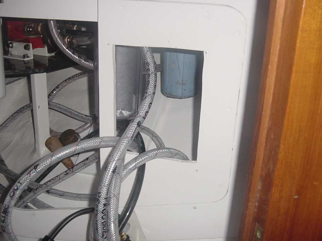
Removing the motor/pump deck resolved the real hindrance to maintenance of the water maker system. I had provided an access port on the front panel that covered the area where the water maker was installed. I had thought this access port would be able to provide the access necessary for proper maintenance. It did not. Two problems came up. The first was that I had attached the sediment filter housings directly to the bottom shelf in the pantry, and the second was that the bottom shelf was not in two pieces, which would have allowed me to make shelf removals more efficient. Other issues came also up, but I am getting ahead of myself!
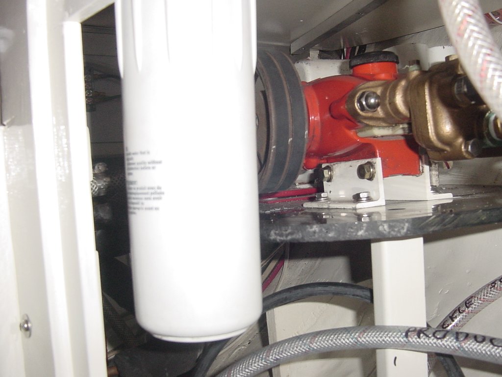
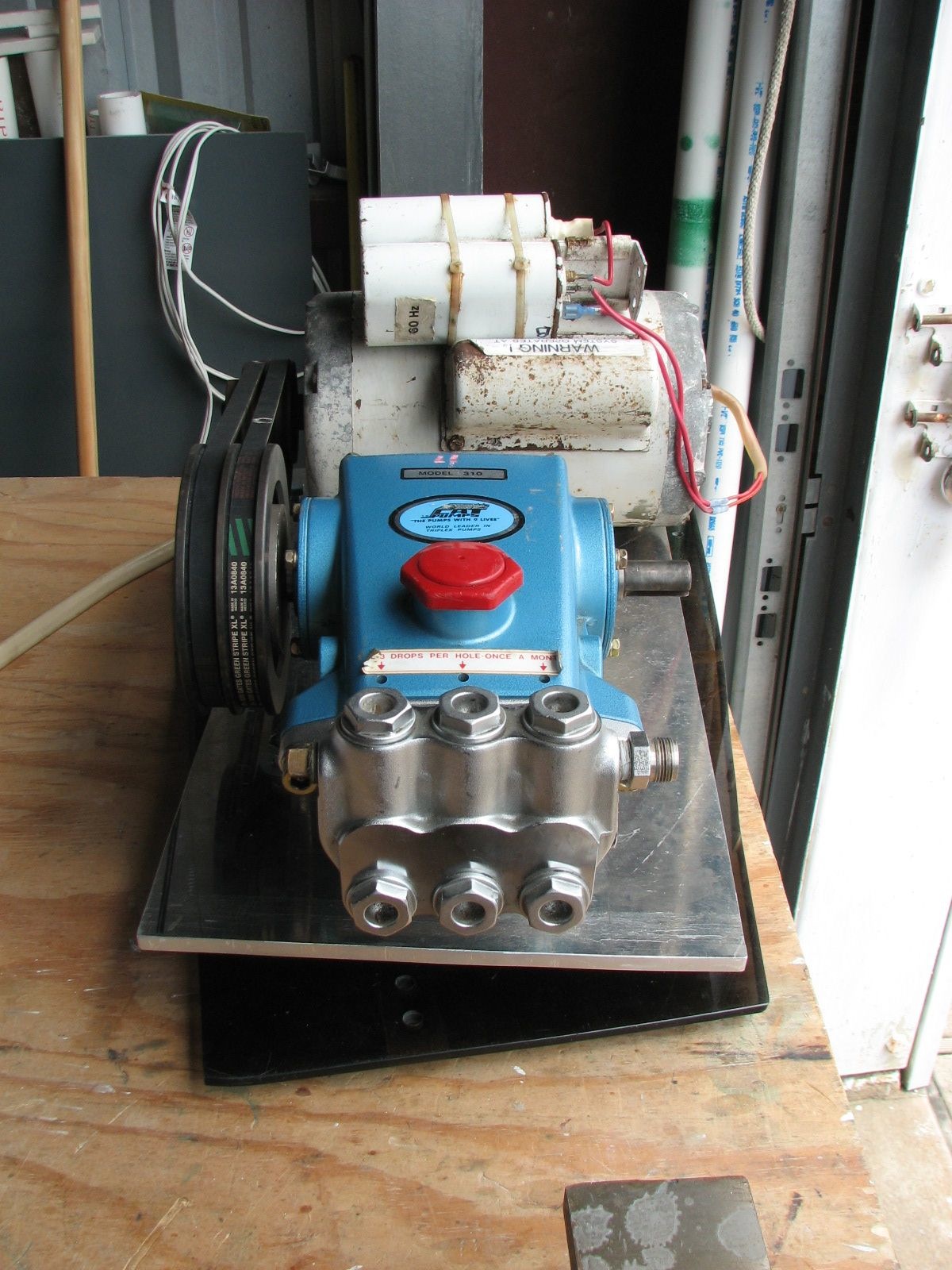
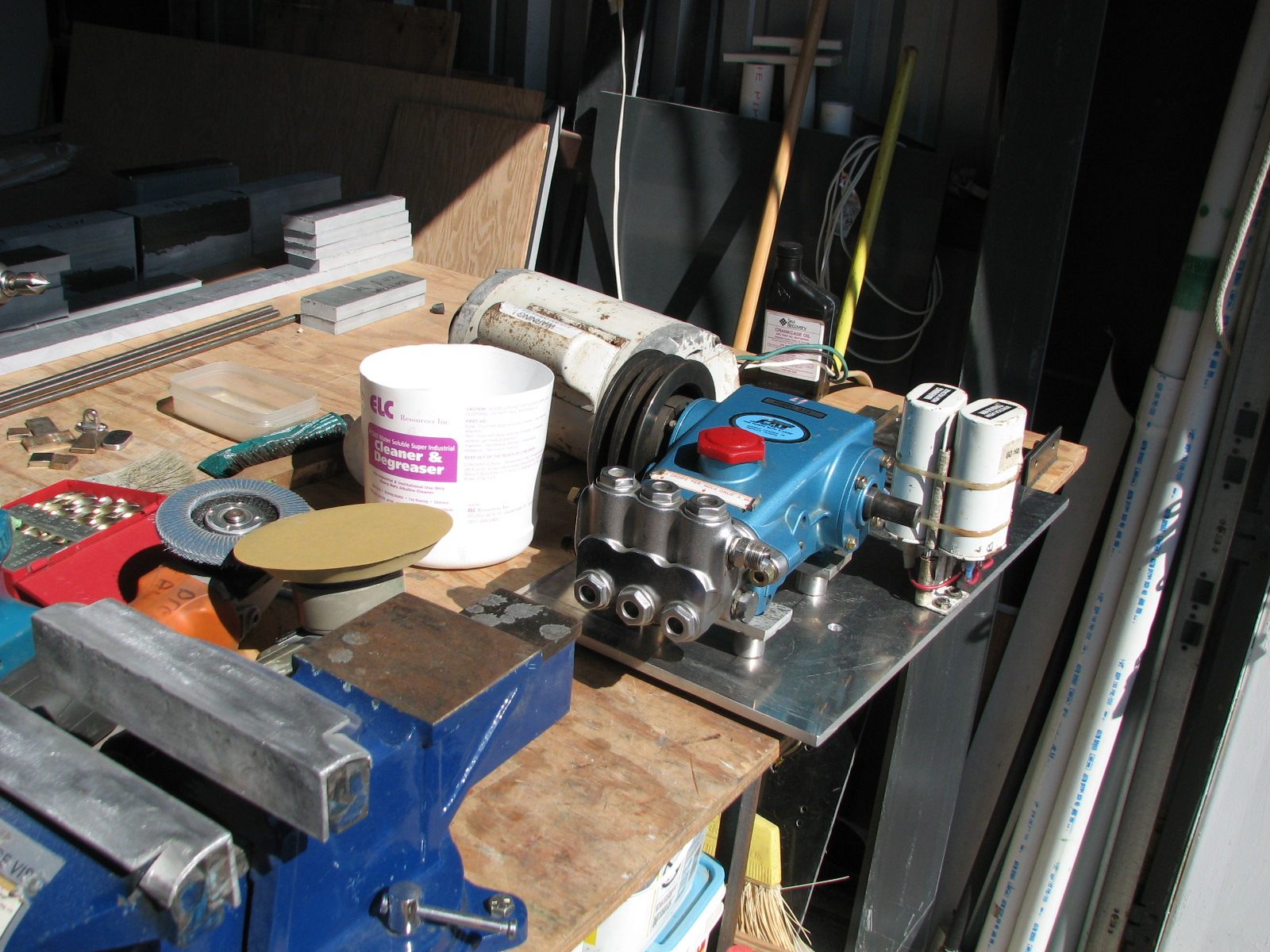
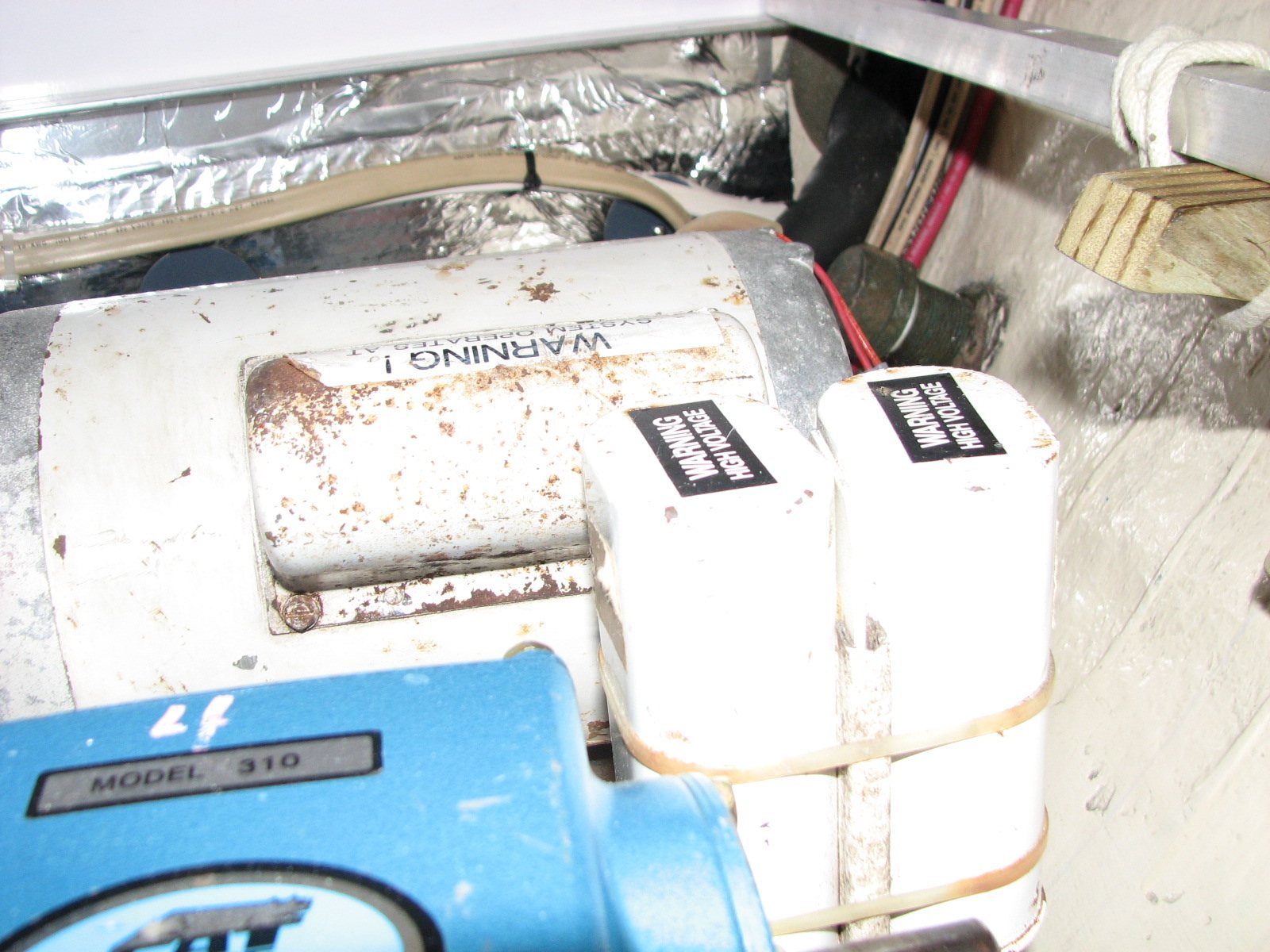
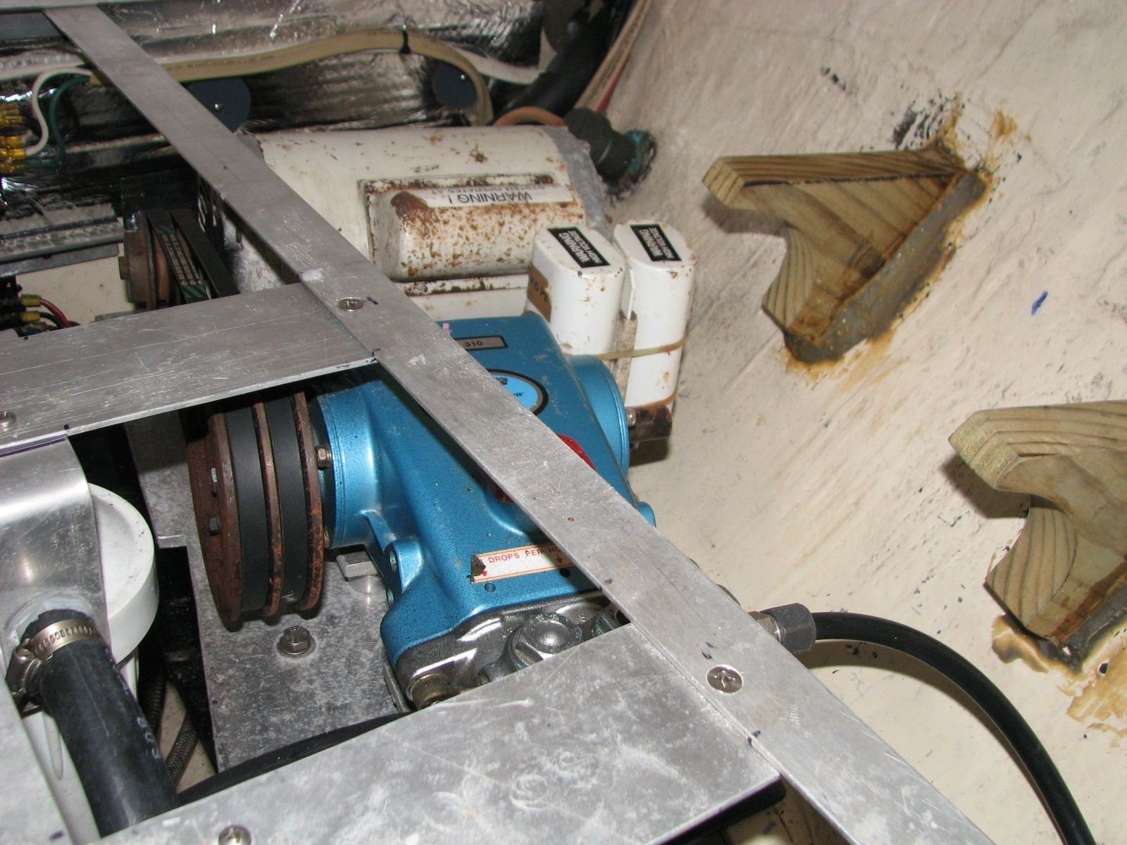
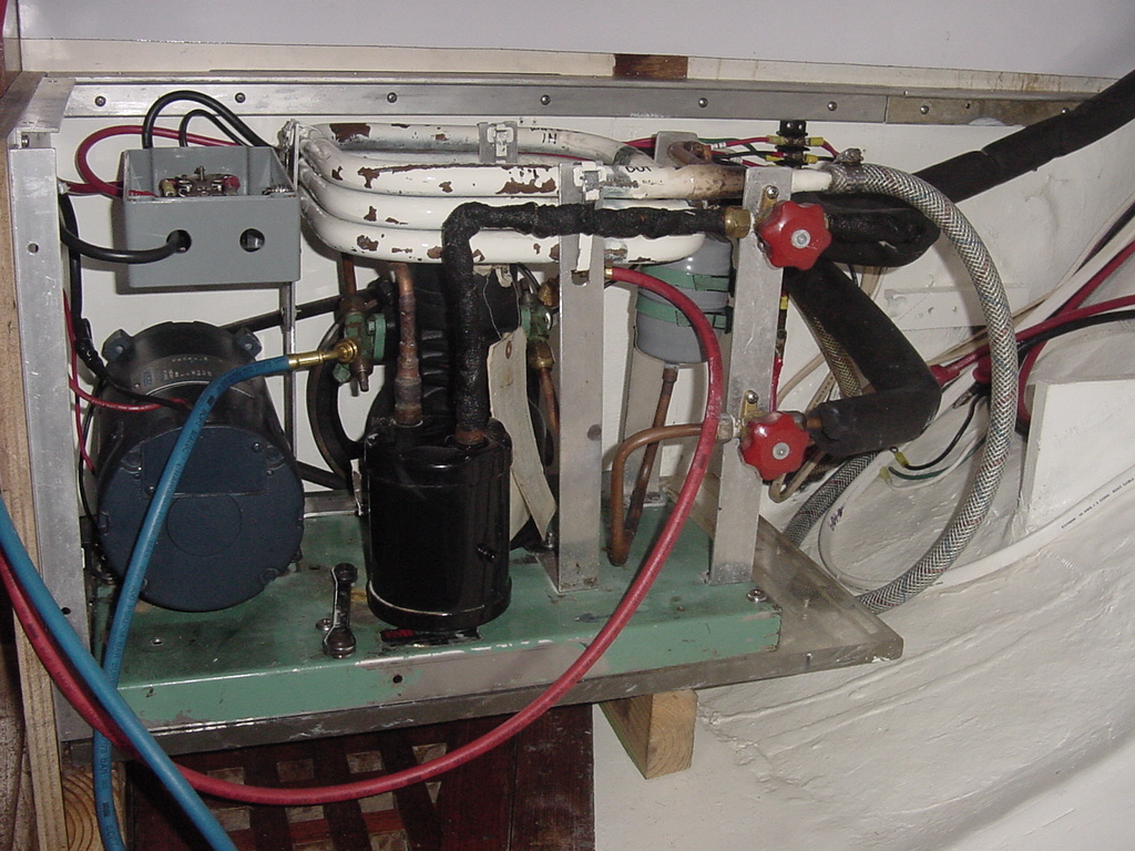
As I mentioned, I removed the motor/pump deck so that I could get to the Hotsy high pressure pump. The Hotsy pump is actually a CAT pump that was an OEM product from Hotsy. Enough history, my pump was very old. Neither Hotsy nor CAT made the pump any more, and I could not find any parts for the pump. I even searched on eBay for a couple of months, but nothing ever came up. At that time, I decided I would have to get a new pump, and I also decided it would be a CAT pump that was still being manufactured, and one for which I could obtain spares. I decided on the CAT 310 Pump. This pump met all of my needs as far as pressure, volume of water needed, and RPM. The CAT 310 Pump was also still being manufactured, and there were plenty of spares available. The pump is used widely in automated car washes. I started my searches on eBay, and before I was finished, I was able to get three CAT 310 Pumps , and enough spares to rebuild a pump twice. The pumps were all used, but in great workable shape, and I did not pay over $300.00 for any one of them. In fact, I purchased a CAT 310 Pump with an attached Baldor 2 HP motor for just $300.00. It turned out the motor was an industrial motor and physically too big for my needs. I was able to sell just the motor on eBay for $300.00, and then bought a spare Baldor 1.5 HP motor for $150.00 on eBay. The whole deal was amazing! I got a third spare pump, a spare drive motor, and $150.00 back in my pocket, just for being patient and being attentive to what was on eBay!! The extra icing on the cake was that the person who purchased my motor was local, so I did not even have to box it up and ship it.
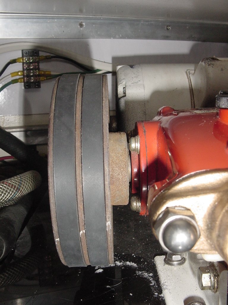
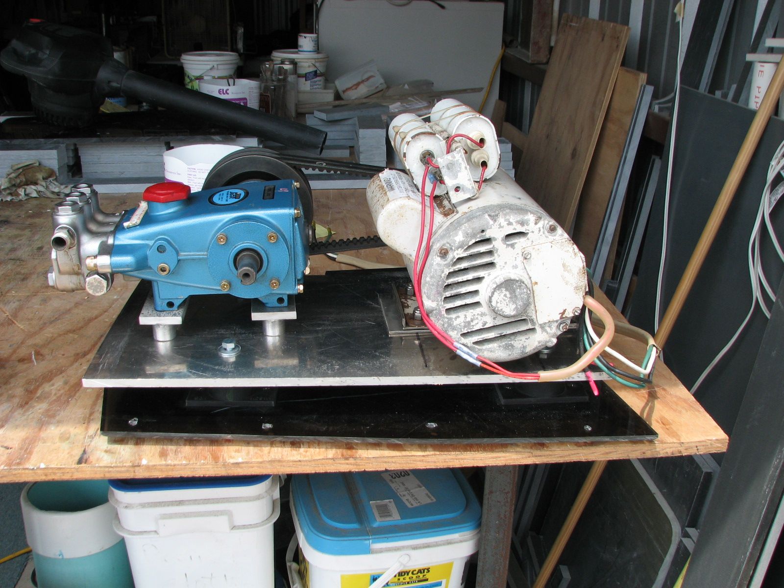
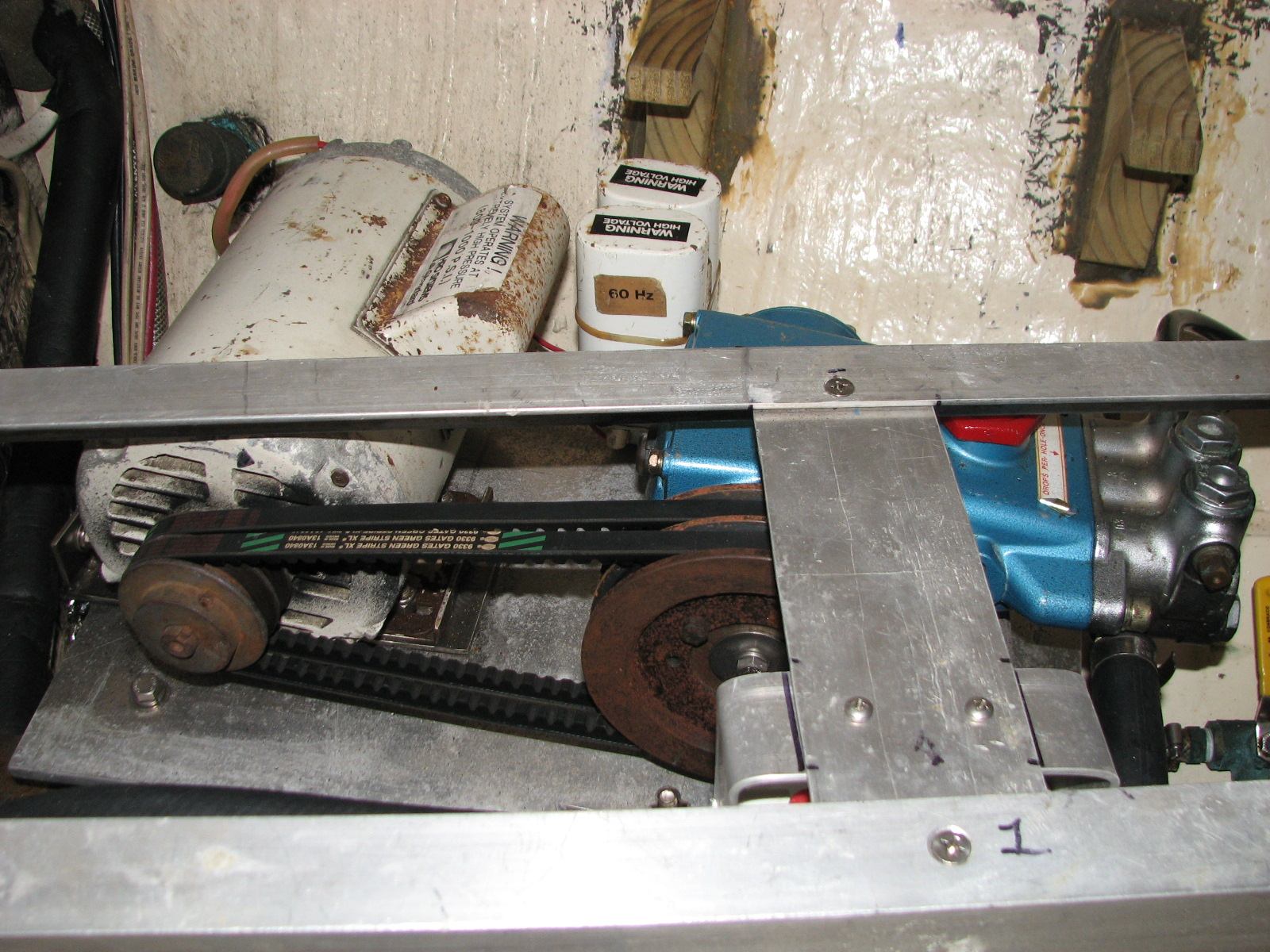
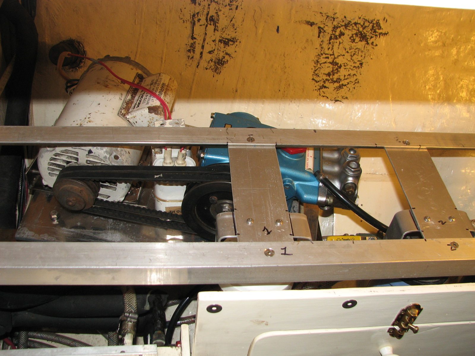
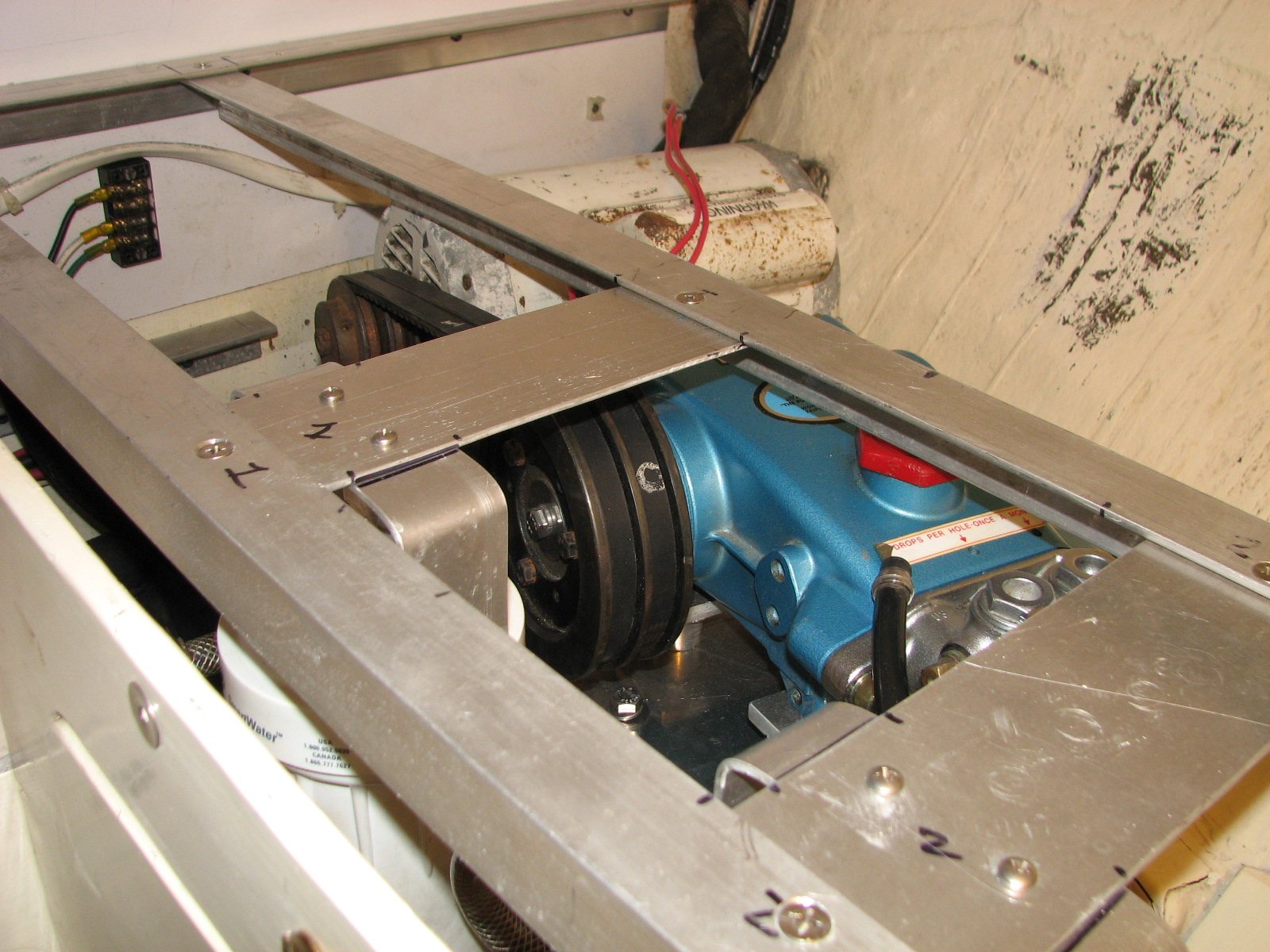
It has been almost three years since I made these changes to the water maker, and we have had very good service out of the system. Now I have to add the BUT!! This new CAT 310 Pump is a great pump, but it was longer, taller and wider than the Hotsy. The pump shaft size was bigger on the new pump, and the pulley on the new pump had to be changed so I could get the correct RPMs to produce the needed pressure. This meant I would have to fabricate a new deck for the motor and pump. As I mentioned in the first pass, I used a piece of 1/2" acrylic plastic for the deck so that I could avoid rot and corrosion problems. Good thought, but the plastic had a problem. When making water, all the parts got hot. The plastic deck would actually warp, and then the drive belts would loosen. I would notice the loose belts, but after everything cooled off the belts would be tight again. Since I had to make a new deck anyway, I decided to go with a piece of 1/2" aluminum plate.
Another change, since I was making a new deck, was to use vibration isolators on the deck to cut down on the noise and vibration that was transmitted to the hull. On the First Pass, the plastic deck was directly connected to the hull, and the noise was not pleasant when we were making water. For the new deck, I put the plastic deck back and bolted it directly to the hull. Then I attached the four vibration isolators to the plastic deck and put the new 1/2" aluminum plate on top of the vibration isolators. I then matched a new pulley for the pump with the pulley on the motor so I could get the correct RPMs and generate the 5 GPM necessary to produce at least 15 GPH of fresh water per hour.
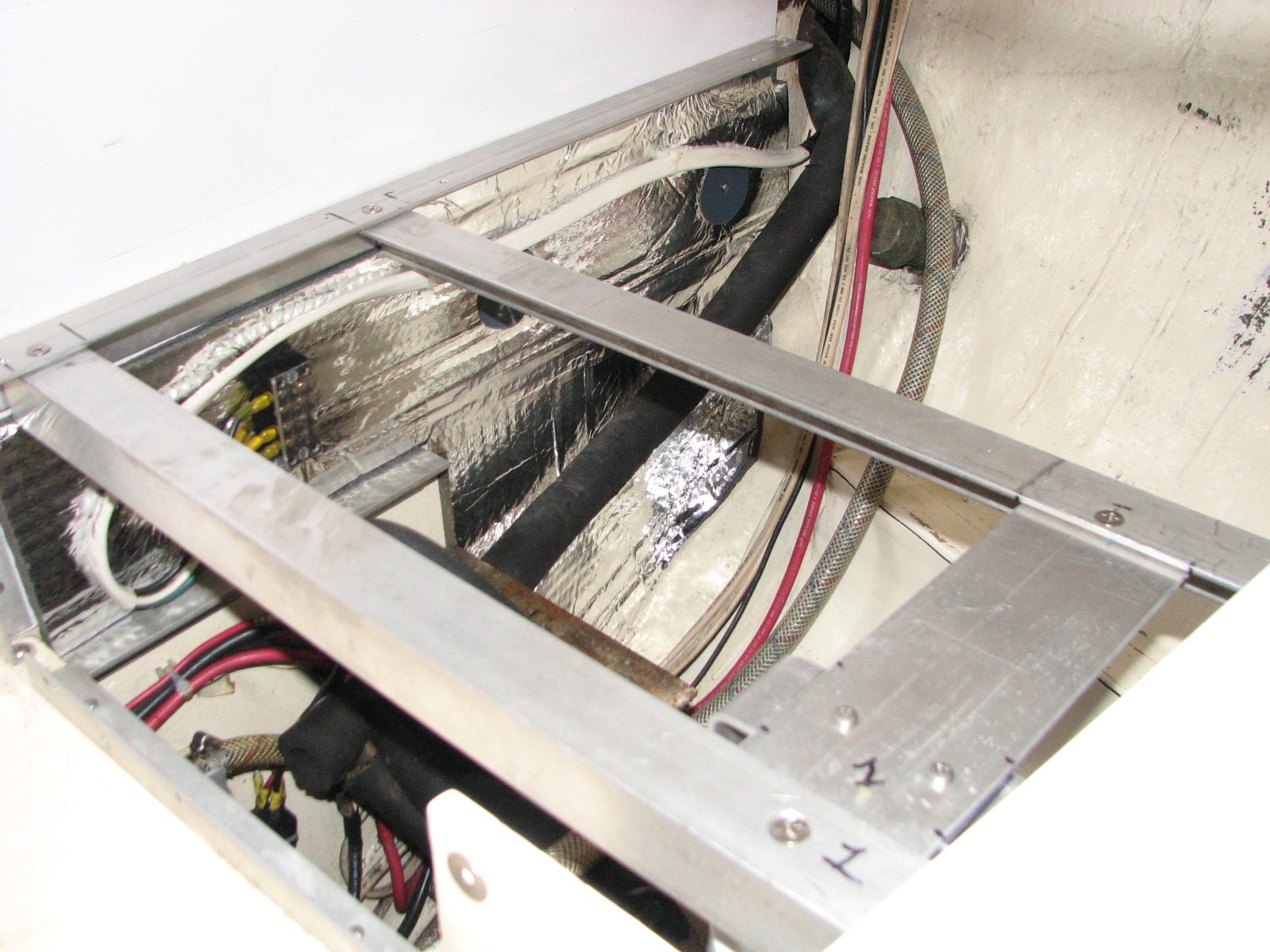
Once I got the deck completely fabricated in my shop, I then had to take it to the boat and make sure it would fit in the allotted space. I waited until I finished the frame for the sediment filter housings so I could be sure I could get the deck with the motor and pump out of the area without any more parts having to be removed. This took care of the water maker high pressure pump problems.
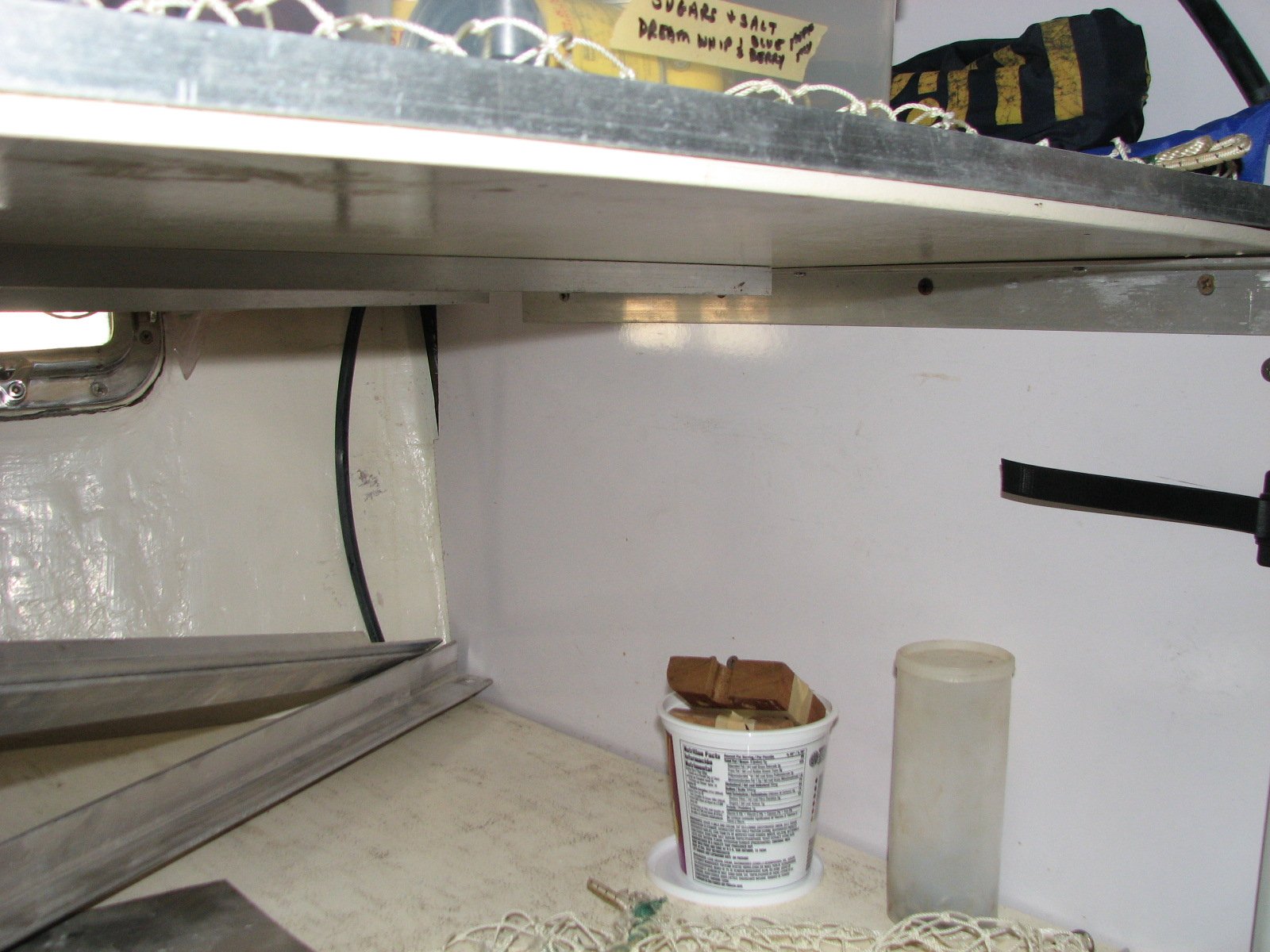
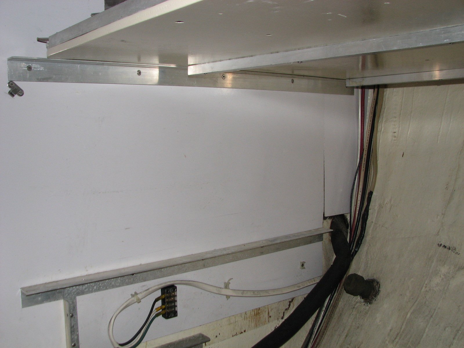
Next, I needed to work on the maintainability of the system, and the restricted access issues. As I mentioned before, the bottom shelf in the pantry was not in two pieces, and the sediment filter housings were attached directly to the shelf. To work on the water maker, I would have to remove the first shelf of the pantry. Of course, this meant that I had to remove all of the baskets and crates that were on the shelf, then disconnect the sediment filter housings, and then remove the shelf, right? WRONG! Because of the sizes and layout of the shelves, I also had to remove the second and third shelves, to be able to remove the first shelf. And, of course, all of the boxes and crates on the second and third shelf had to be removed first. By then, I had the main cabin filled with the all of the supplies from the pantry, and I had not even started working on the water maker. All this is just to check the oil in the high pressure pump. Ridiculous! Not a workable solution!
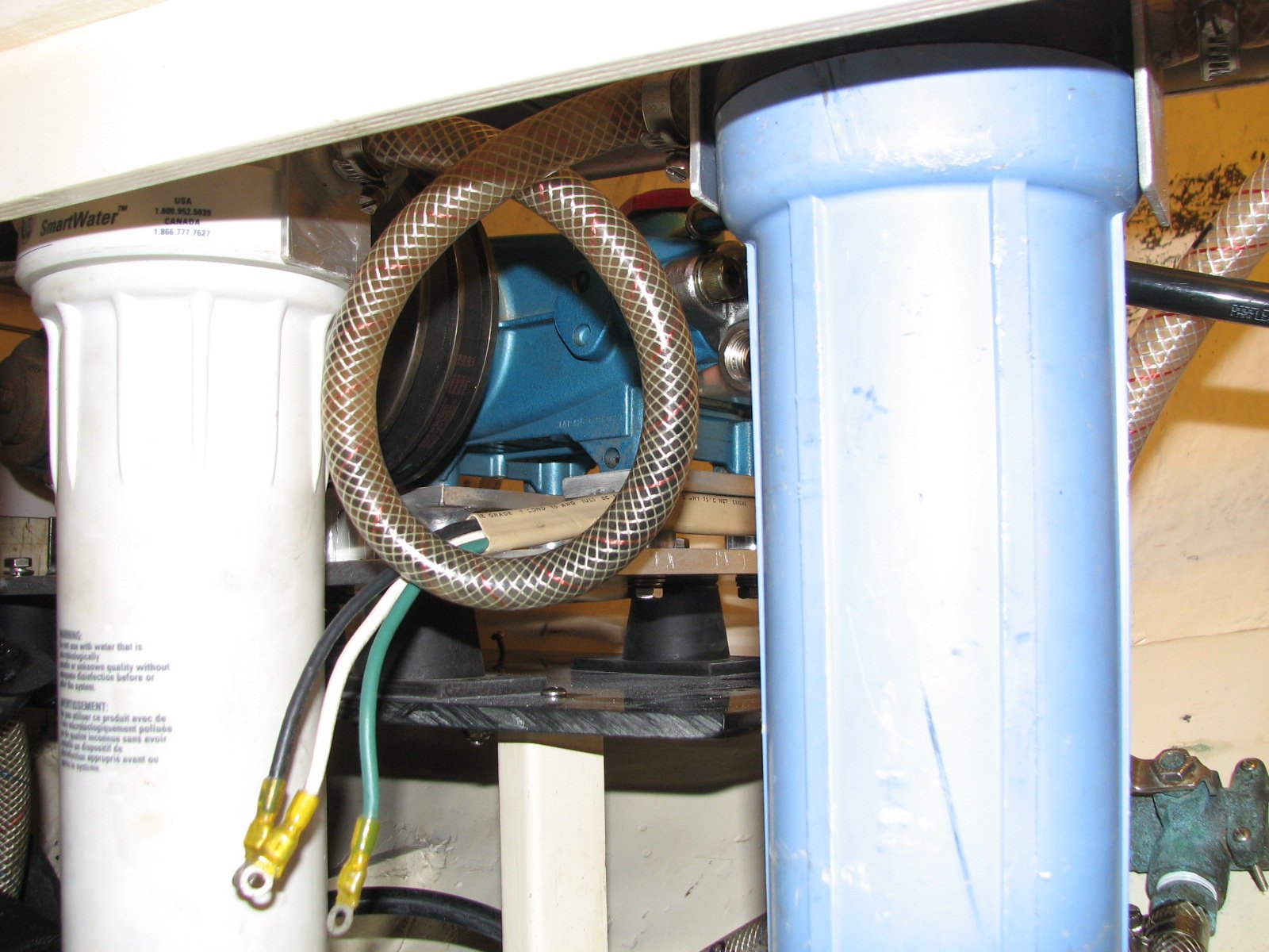
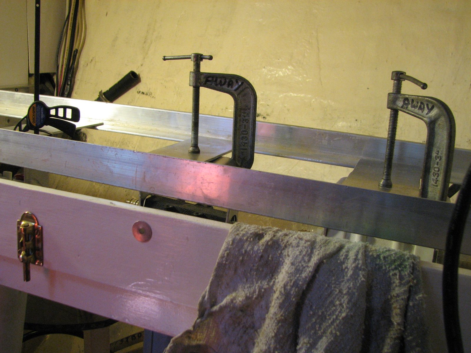
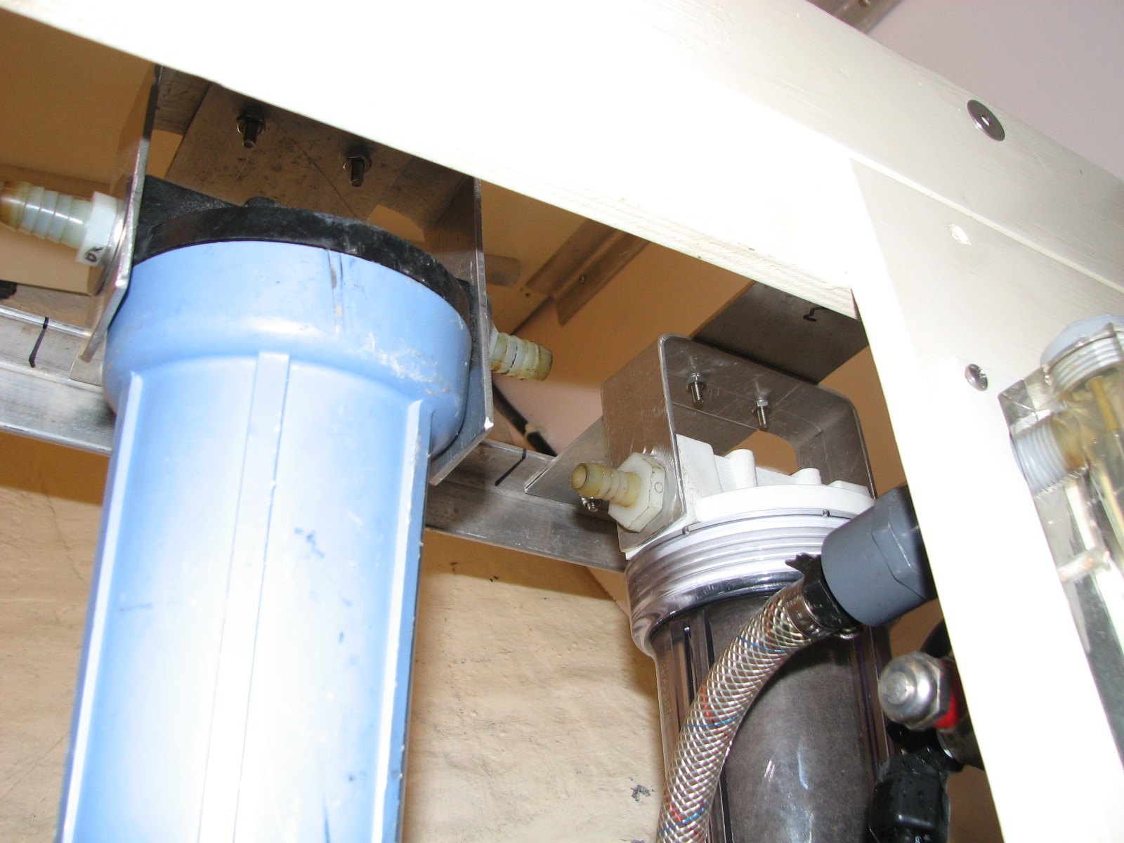
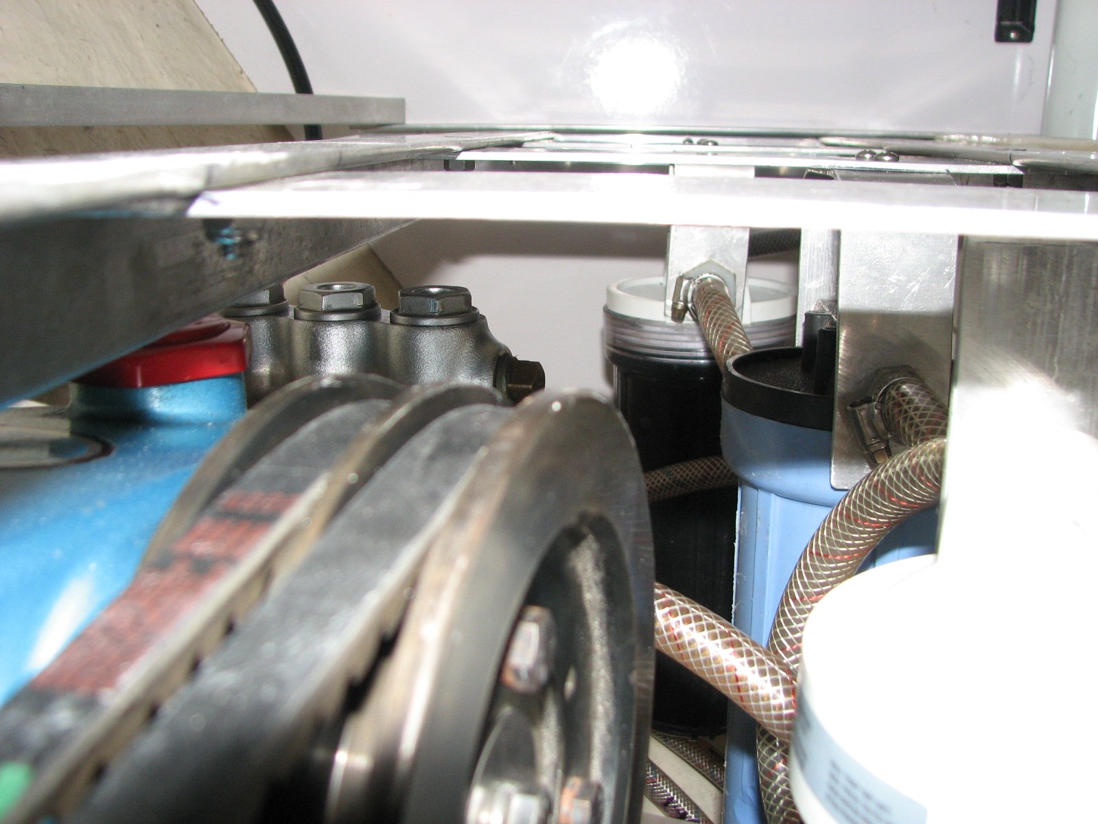
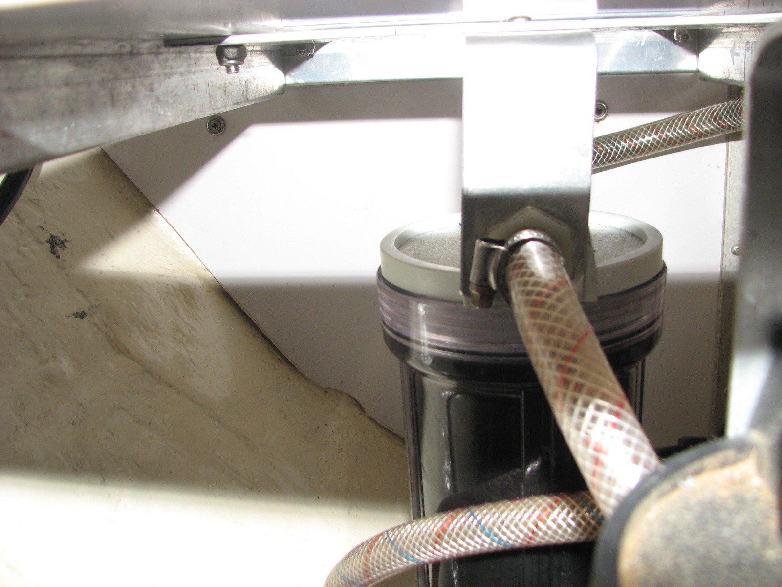
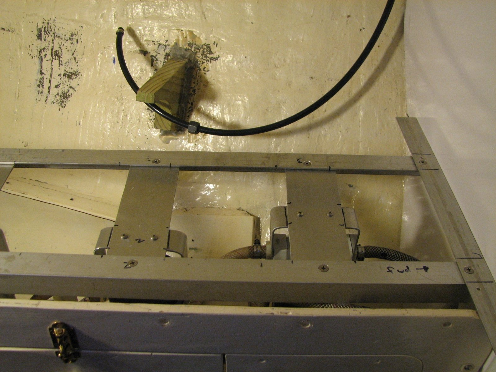
So my plan was to build a frame from which to hang the sediment filter housings. The other task was to cut the first shelf in the pantry into two pieces. I did this because the motor and the high pressure pump are actually located at the back half of the area. With the shelf now in two pieces, I had only to remove the crates and boxes from the back half of the first shelf to gain access to the major components of the water maker system. When I built the frame for the sediment filter housings, it was actually below the first shelf, which made it much easier to work on from the front panel access port. Since I was cutting the first shelf into two pieces, I had to add support for the back of each shelf. This necessitated fiberglassing supports to the hull as the supports for the shelf halves.
As mentioned in the previous paragraphs, to get started on this project, I had to remove all three shelves in the pantry, and all of the boxes and crates on them. Once the bottom shelf was removed, I could put the second and third shelves back into the pantry, and all of the stuff on them. Then I was able to work on the first shelf and the new framework for the sediment filters.
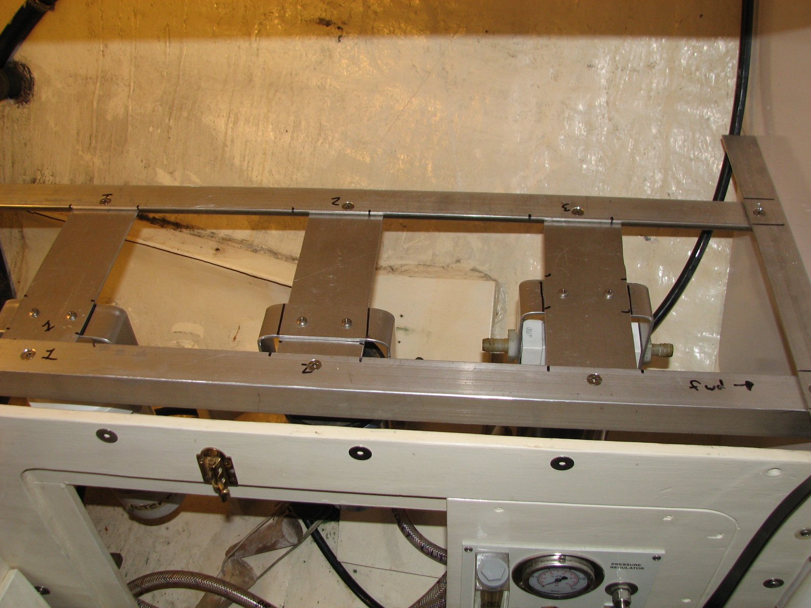
Next on the list was to actually construct the framework from which to hang the sediment filters. I purchased the aluminum angle and flat plate to use in the fabrication. I had to mock everything up, and design the offset for the filters so the hoses would fit. I finally got all the filter housings set on the frame. The filter housings were placed so that all of the hoses would fit properly and the housings were out of the way of everything. This made it easy to replace the filters from the access port. Next, it was just a matter of drilling all of the holes, and bolting the framework together.
When the framework was all together, I was able to get the new deck installed with the vibration isolators. All of the planning and mocking up of the housing framework was worth the effort. The new deck with the pump and motor slid right into place. I wanted to be able move the deck in and out with all of the parts attached, just in case it became necessary. Next, I bolted the deck to the anchors that were attached to the hull and bulkhead, and then ran all of the hoses.
I delayed actually testing the system until it was closer to our departure date because once I "un-pickled" the system, I did not want to have to do the pickling process again. Let me just say that the system worked wonderfully once we got into some salt water. The really amazing thing is the membrane filter was pickled for three and a half years, and when put back into service it worked just like it was new. At some points, depending on the salinity of the water, I was able to get 20 GPH out of the system. For me that proves the value of properly pickling the membrane filter, when the system is not in use.
The last item to complete the water maker upgrade was to cut the bottom pantry shelf in half, and fiberglass the two shelf supports to the hull. The bottom pantry shelf was supported by angle aluminum braces attached to the pantry forward and aft bulkheads. When the shelf was cut into two pieces, it would be necessary to have supports on the back of each half of the shelf. The only difficulty of these supports was getting the proper angles on the hull side and the shelf side. With patience and templating, I was able to get the two supports cut to the proper shape, and glassed to the hull.
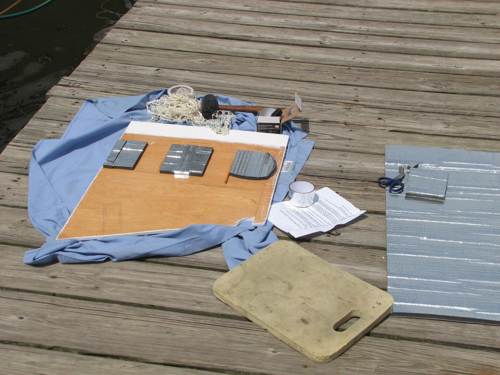
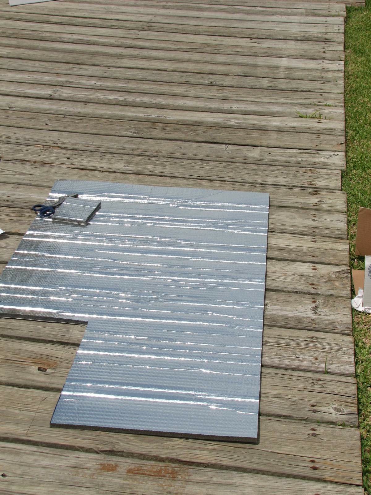
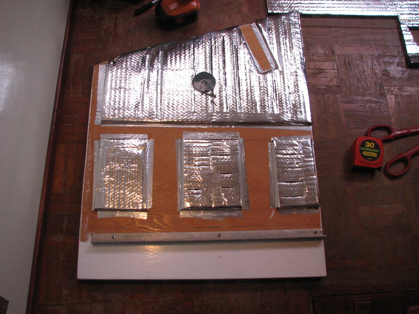
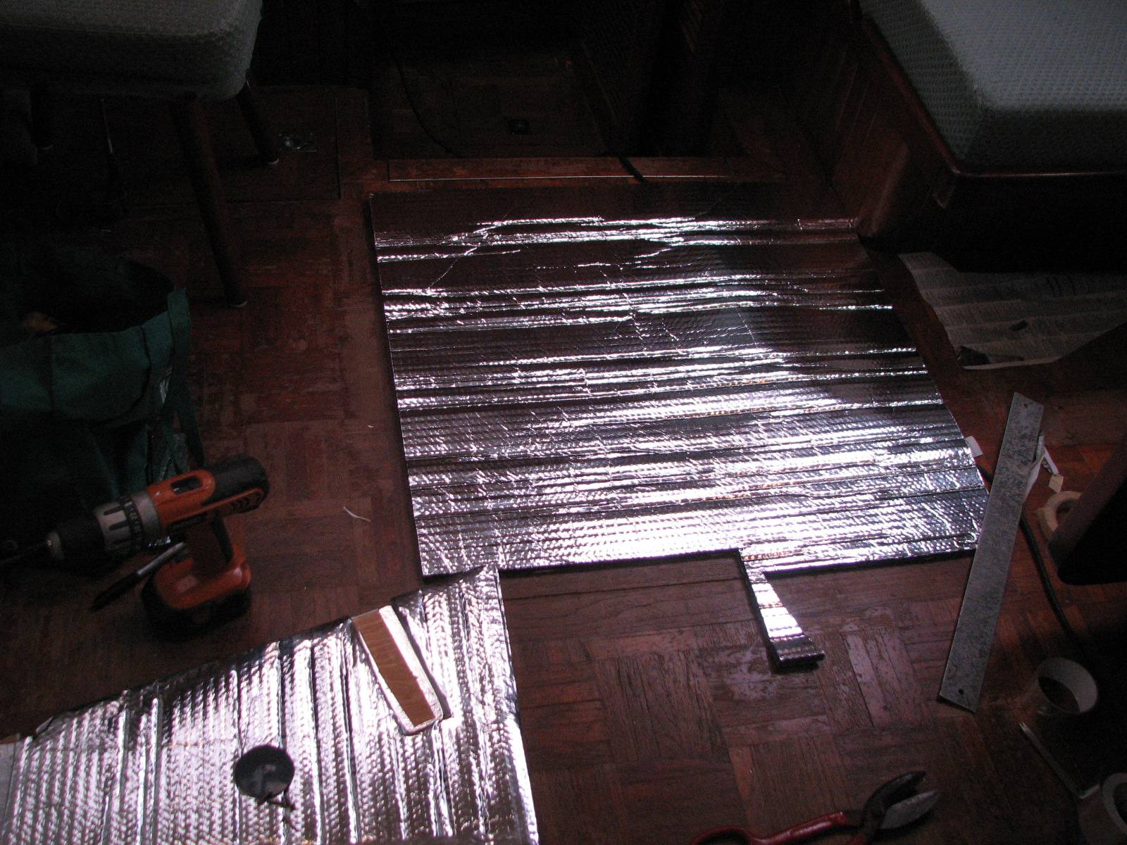
I do want to mention that I was determined to install as much sound proofing as possible in the area for the refrigeration motor and compressor, and the water maker motor and pump. This one area houses both systems. As mentioned previously, I had installed vibration isolators on the water maker deck and they helped a lot. Now I approached the soundproofing by installing the same composite material I had used to soundproof the engine room.
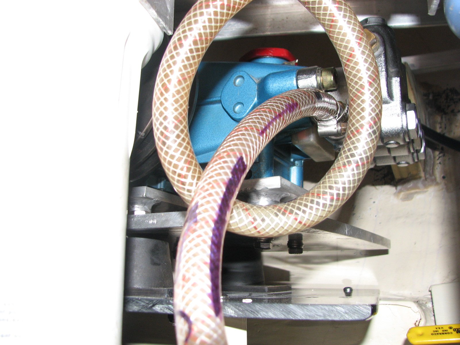
Another change I made was a different lift pump for the system. If you recall from the First Pass discussion, I originally used a Jabsco Sensor Max pump for the lift pump. Also, as was noted, this pump was sharing duties as the water maker lift pump and the raw water wash-down pump. The Jabsco Sensor Max could not keep up with the upgraded system and the new CAT 310 Pump. I needed a new lift pump for the upgraded water maker system.
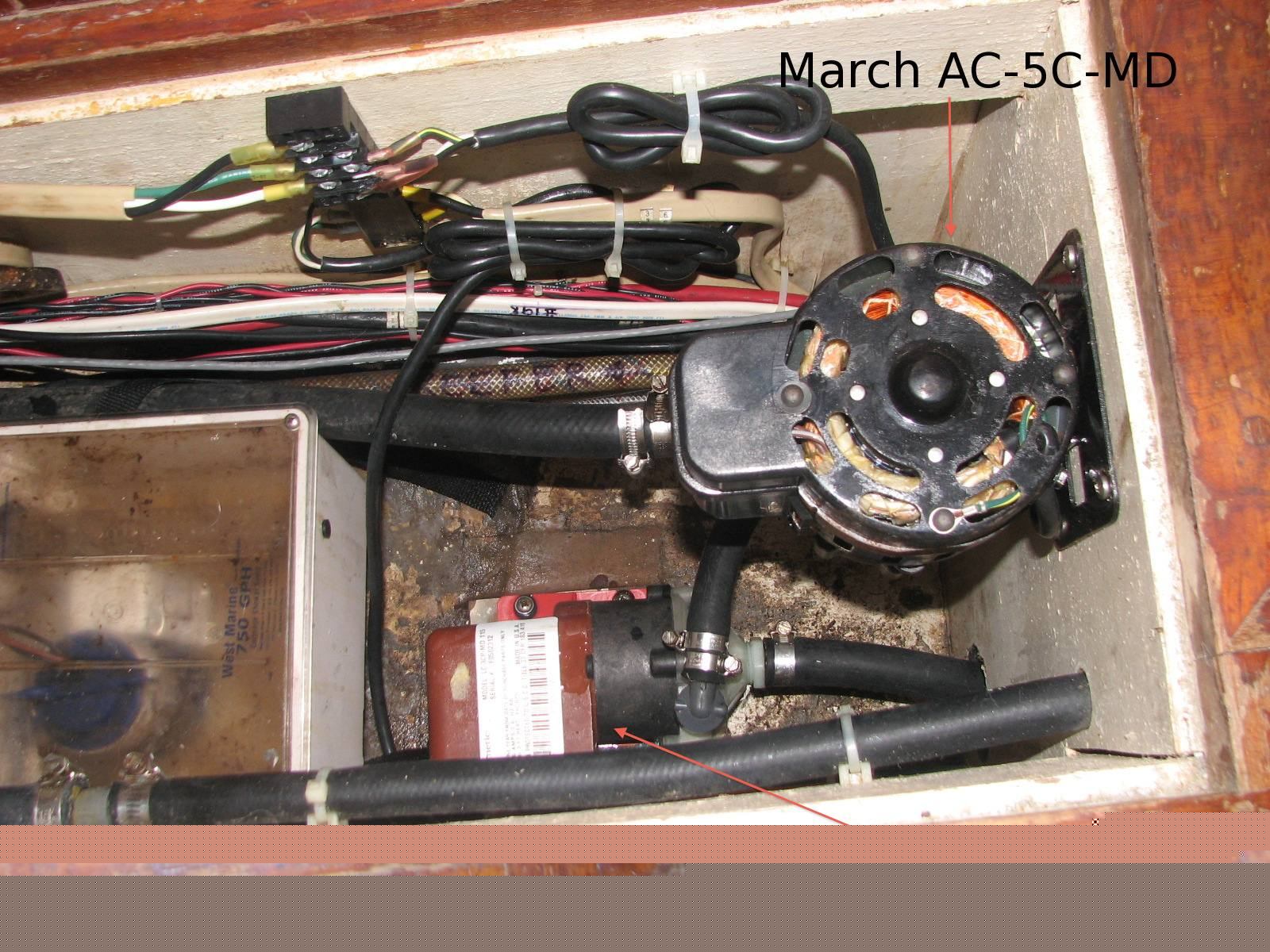
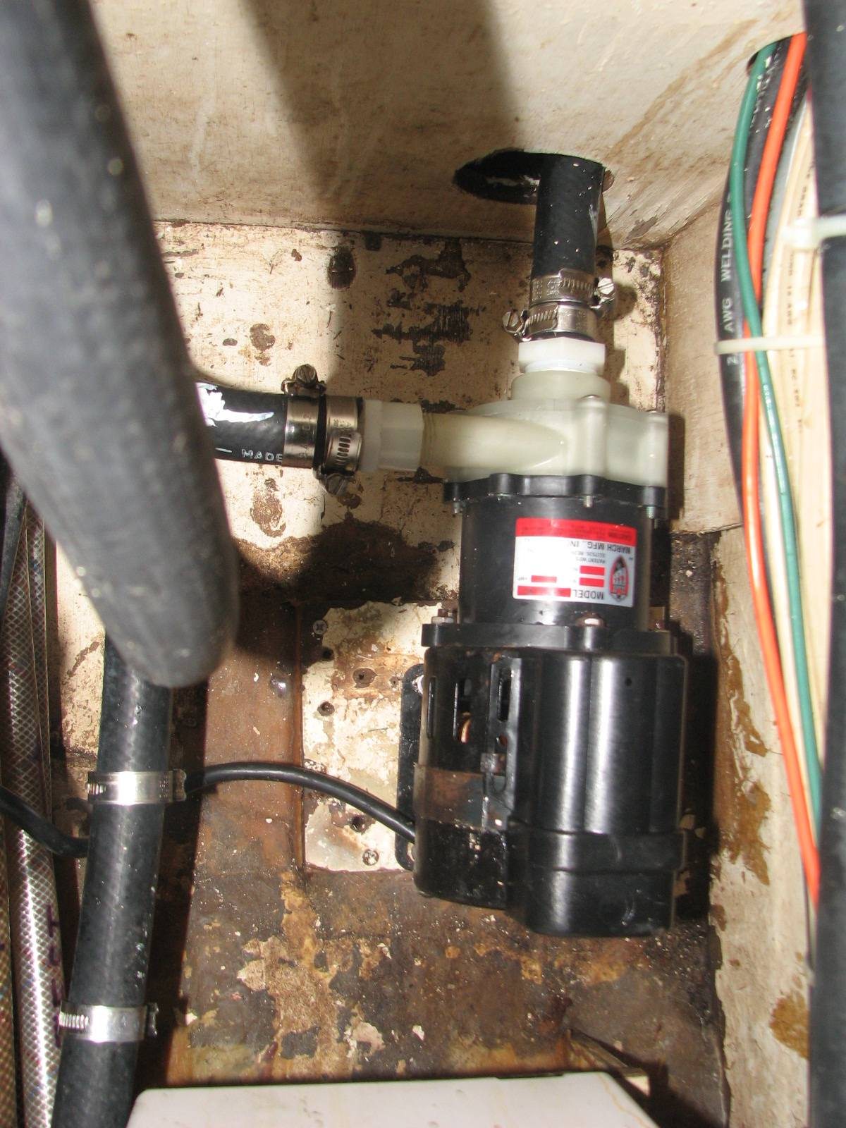
The decision on which pump to choose was based on several considerations. First and foremost was capacity. Next in line was with what system was I going to share the pump? The raw water manifold system I have on DREAM AWAY was maxed out. I also did not have any place to add a dedicated pump to the water maker system. The pump I finally decided on was the March AC-5C-MD. This pump had the capacity required, and is actually used as an air conditioning cooling pump. I also decided to share the March AC-5C-MD pump with my forward air conditioning system. The pump I was using to cool the forward air conditioning system, was a March LC-3CP-MD.
The good news about this decision is that the new March AC-5C-MD pump has a much higher capacity than the original March LC-3CP-MD, 17 GPM verses 8.5 GPM. When I removed the March LC-3CP-MD pump, it became the spare cooling pump for the aft air conditioning system, a real plus. The down side of the new March AC-5C-MD pump is that it is powered by 120 VAC, rather than 12 VDC, as the Jabsco Sensor Max pump was.
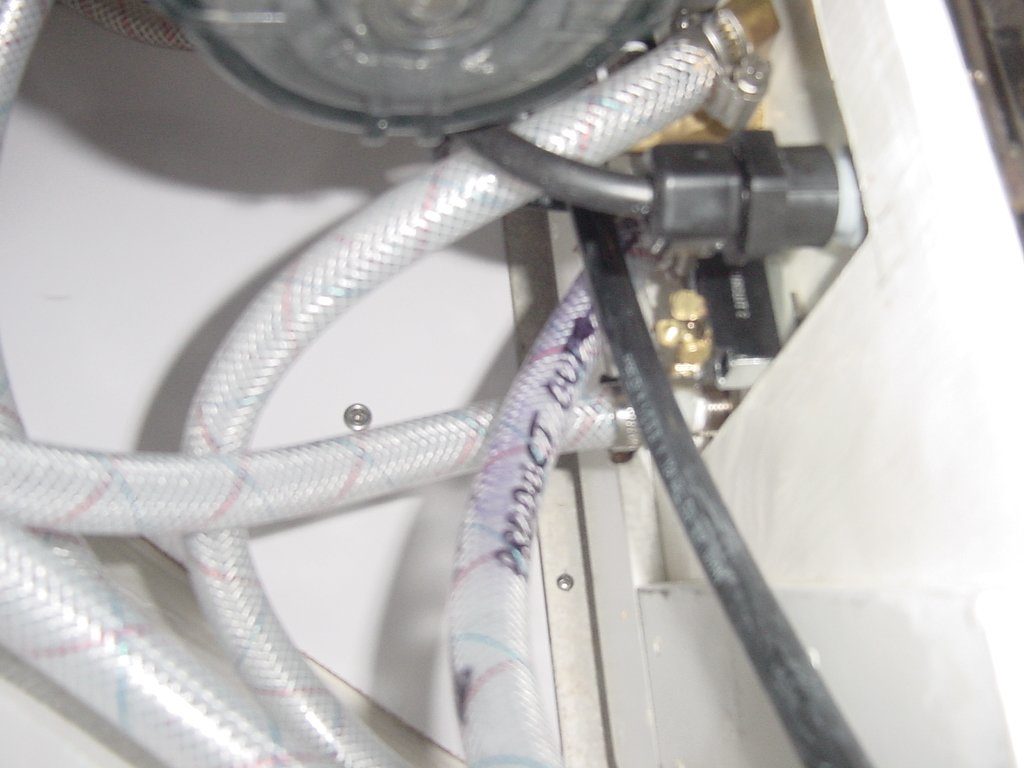
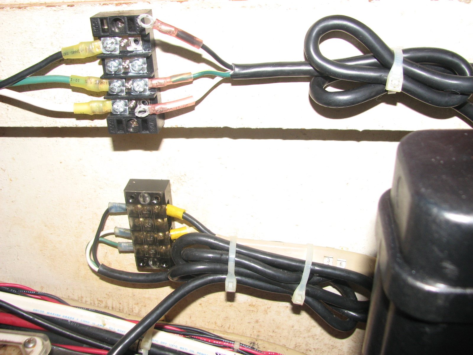
The power to the pump would have to be switched depending on whether it was used by the forward air conditioning system or the water maker system. The output water from the pump would also have to be switched depending on which system was in use. I decided to use a relay that would switch AC power. When the relay was not activated, or normally closed, it would provide AC input power to the pump to cool the air conditioning system. I did this because the air conditioner is used much more than the water maker. When the air conditioner is off, and power is applied to the relay via a breaker on the electrical panel, the AC input power is sent to the pump. I can manually switch the water output from the pump with the valve I used when I was switching water between the raw water wash-down and the water maker.
I have to make sure the air conditioning system is off before getting water to the input for the high pressure pump of the water maker. Then I switch the output water from the pump to the water maker system. Next, I activate the breaker on the electrical panel to start the pump, and switch on the breaker for the motor that drives the high pressure pump for the water maker system. Then I can start making water.
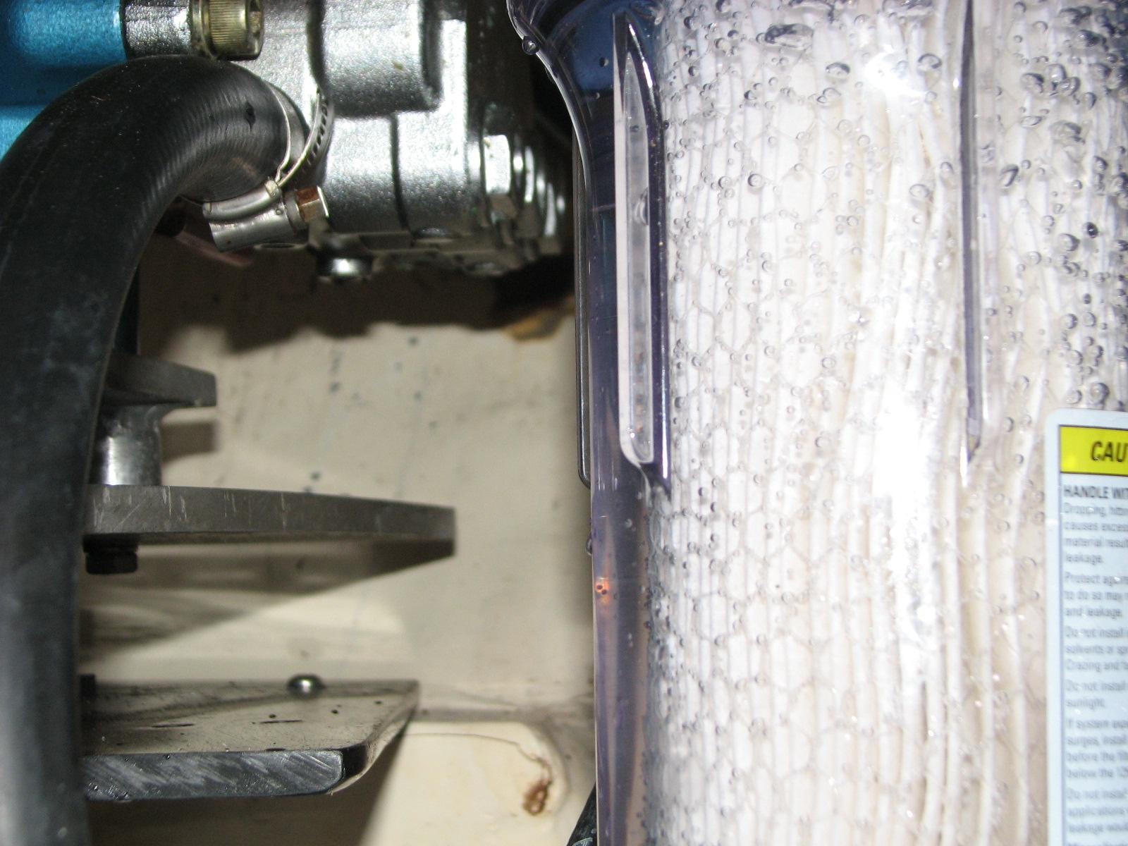
The latest change I made to the water maker system was in response to a problem that would sometimes occur. Depending on the salinity of the water being filtered, the high pressure pump might be starved for input water. I though the problem was because of the size of the hose being used to supply water to the high pressure pump. The hose from the feed pump to the first sediment filter is 3/4". The output of the first sediment filter is 1/2" hose, because the second sediment filter housing would only accept 1/2" hose. From there on, the system used 1/2" hose right up to the high pressure pump. I purchased a new housing that would accept the 3/4" hose, and I made sure the housing was clear plastic so I could see what was going on inside the housing. I then installed 3/4" hose from the lift pump all the way to the high pressure pump. This, of course, necessitated all new hose fittings and barbs so that the new hose would fit. Fortunately, this upgrade pretty much made the problem go away.
Now I have a water maker system that I can more easily maintain, and I have plenty of spare parts with which to maintain it. Since adding in the CAT 310 Pump, the system has consistently made more than 15 GPH. Most of the product water is produced at 18 - 20 GPH when I keep the pressure at around 700 psi. I could probably go higher on the pressure to make more water, but I do not want to strain the system. I have a new drawing of the complete Second Pass system. There are not many changes, but I thought it best to be accurate. I have also upgraded the parts list.


